background image

03/2003 

4-126

8850/ 510DP

REP 10.5, REP 10.6

Repairs and Adjustments

3.

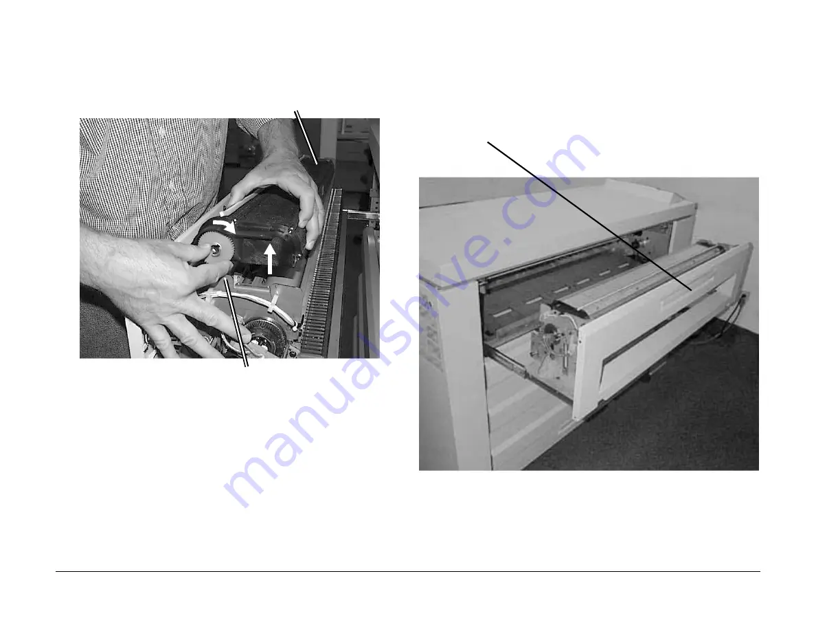
(Figure 6): Reinstall the Web Oiler Assembly on the Printer.

Figure 6 Reinstalling the Web Oiler Assembly

4.

Return the Printer to normal operating condition.

5.

Enter the Printer diagnostics and perform the following:

a.

10-30 Web Oiler Parameters Reset - to reset the meter if a new Web Oiler is
installed.

b.

10-31 Partial Web Oiler Parameters Reset - to reset the parameters for a partially
used Web. Measure the diameter of the remaining web on the Supply Roll in millime-
ters and enter this value. 

REP 10.6 Thermal Fuse (F1)

Parts List on 

PL 10.2


Removal

1.

(Figure 1): Access the Fuser Module.

Figure 1 Accessing the Fuser Module

2.

Remove the Fuser Heat Roll (REP 10.2).

1

Position the Web Oiler Assembly so 
that the drive side is on the right side of 
the Fuser Drawer

2

Slide the two prongs on the left 
side of the Web Oiler Assembly  
into the slots on left side of the 
Fuser Drawer

3

Lift the right side of the Web Oiler 
Assembly slightly and turn the 
Takeup Roll clockwise to remove 
any remaining slack in that roll

4

Set the Web Oiler back down on 
the Fuser Assembly and tighten 
down the two mount screws

1

Pull up on the handle and pull open the 
Fuser Module Drawer.

Summary of Contents for Synergix 8850

Page 1: ...03 2003 1 8850 510DP Transmittal Page Transmittal Page 3...

Page 2: ...03 2003 2 8850 510DP Transmittal Page...

Page 3: ...the Synergix Print System SPS 510dp printers Photographs and illustration may show the external view of the 8850 however the procedure can also be done on the SPS 510dp Some of the covers may latch an...

Page 4: ...Line Current Limit to add 115 VAC 20 Amp service for 510dp running 5 and 7 D A1 size prints per minute Revised ADJ 10 2 Fuser Drive Interlock Switch 8850 W O TAG 8 Interlock Switch is only adjustable...

Page 5: ...03 2003 1 8850 510DP Title Pages Title Pages...

Page 6: ...03 2003 2 8850 510DP Title Pages...

Page 7: ...ers Service Manual THE DOCUMENT COMPANY XEROX CAUTION Certain components in the 8850 Printer and SPS 510dp are susceptible to damage from electrostatic discharge Observe all ESD procedures to avoid co...

Page 8: ......

Page 9: ...03 2003 1 8850 510DP Introduction Introduction About this Manual iii Organization iii How to Use This Manual iv Repair Analysis Procedures RAPs v Repair Adjustment Procedures v Reference Symbology vi...

Page 10: ...03 2003 2 8850 510DP Introduction...

Page 11: ...identify and classify the problem and to refer you to the appropri ate RAP in order to repair the problem When the problem has been repaired perform the Final Action Print Defect Isolation Procedure T...

Page 12: ...exit the pro cedure when the fault is fixed Do not perform the remaining steps Section 4 Repair Adjustment This section contains the repair and adjustment procedures for the 8850 Printer Section 5 Par...

Page 13: ...ow to remove and replace components The adjustment procedures provide detailed steps on how to check and adjust components Some units have been modified by various design changes Each change or modifi...

Page 14: ...03 2003 vi 8850 510DP Introduction Reference Symbology Figure 1 The following symbols are used in this document Figure 1 Reference Symbology 1 of 2...

Page 15: ...03 2003 vii 8850 510DP Introduction Figure 2 Reference Symbology cont d Figure 2 Reference Symbology 2 of 2...

Page 16: ...03 2003 viii 8850 510DP Introduction...

Page 17: ...n 1 3 Call Flow Call Flow Procedure 1 4 Initial Actions Systems Checks 1 4 Print Defect Isolation Procedure 1 5 Workstation Checkout Procedure 1 5 Status Code Entry Chart 1 6 Message Display Entry Cha...

Page 18: ...03 2003 1 2 8850 510DP Service Call Procedures...

Page 19: ...rints PING tests and tests made from a laptop PC Status Code Entry Chart This table contains a list of Status Codes their related compo nents the corresponding RAP Repair Analysis Procedure BSD Block...

Page 20: ...Setup Menu Performing printer diagnostics Viewing recent fault log to have the customer review the fault log 5 Analyze the frequency of the fault codes and refer to the Status Code Entry Chart to trou...

Page 21: ...rom the workstation If the file prints OK then the original file might be corrupt 2 If the workstation is connected to a network go to step 3 Otherwise go to step 5 3 Ask the customer to obtain the IP...

Page 22: ...7 3BSD 7 3 PL 7 2 PL 7 4 C2 07 No RAP Roll 1 Position Sensor error Media was not detected at the Roll 1 Position Sensor when feeding from Roll 2 Roll 1 Position Sensor Q1 Main PWB BSD 7 2 PL 7 1 C3 06...

Page 23: ...be opened and the media to be removed Sheet Feed Sensor A21Q2 Main PWB A3 BSD 8 1 PL 10 7 PL 1 1 Table 1 Status Code Entry Chart Status Code Description Components BSD Ref PL Ref E4 13 No RAP Stripper...

Page 24: ...BTR Detack Corotron Slip Ring Leads Con nectors Main PWB A3 BSD 9 8 BSD 9 4 PL 1 3 PL 8 3 Table 1 Status Code Entry Chart Status Code Description Components BSD Ref PL Ref LL 22 Clean voltage Detack H...

Page 25: ...ntry Chart Status Code Description Components BSD Ref PL Ref LL 52 No RAP Power On Self Test fault or The external RAM failed POST Replace Main PWB A3 PL 1 1 LL 53 No RAP Power On Self Test fault IOT...

Page 26: ...L 1 1 LL 7D No RAP CRC Check Failure Replace the AC Module Assembly A1 BSD 10 1 PL 1 1 LL 7E No RAP Fuser Controller Firmware Fault Fuser locked in calibration mode due to a firmware fault To reset sw...

Page 27: ...THE MEDIA DRAWER X Refer to Note Drawer X Inter lock switch is open Refer to the display on the Control Panel and follow the clearance proce dure BSD 7 1 PLEASE CLOSE THE FRONT DOOR Front Door Inter l...

Page 28: ...Printer is not opera tional 24 VDC FOR circuit open in the Interlock chain Refer to BSD 1 3 and check for an open in the 24 VDC FOR circuit BSD 1 3 ALL ROLLS ARE EMPTY MediaRegistration Sensor failed...

Page 29: ...le INTERVAL TASK REASON TASK ENABLER Normal Call Clean the Drum cleaner module Clean the Erase Bar Inspect the Drum for damage Inspect components for vellum con tamination Inspect all seals for damage...

Page 30: ...and Sheet Feed Pinch Rolls Reduce the airborne contaminants Wipe down with a lint free cloth and antistatic fluid Normal Call Check and clean or replace the Strip per Fingers Clean the Media Guides Be...

Page 31: ...ears will cause the housing to move up or down which will cause print quality defects Check the gears for worn or broken teeth replace the gears if necessary Ensure that the drive coupling is engaged...

Page 32: ...ia drawers with a vacuum cleaner 400K feet or 122K meters Lubricate the Roll Feed Media Drawer Latches PL 7 5 Machine operation ensure that the drawers close completely Lubricate the Roll Feed Media D...

Page 33: ...nt 0955 5 from the IOT Prints are delivered to the exit tray Y N Go to the Initial Actions to begin your repair Evaluate the prints using Print Defects in Section 3 The print quality is acceptable Y N...

Page 34: ...03 2003 1 18 8850 510DP Callback System Checkout Final Action Service Call Procedures...

Page 35: ...2 9 LL 41 LL 45 LL 81 Fuser Warm up Fault RAP 2 10 LL 90 Overtoned Fault RAP 2 11 09 04 Automatic ESV Setup Failed Condition X RAP 2 13 Electrical Faults 1 1 AC Power RAP 2 14 1 2 DC Power RAP 2 15 1...

Page 36: ...03 2003 2 2 8850 510DP Status Indicator RAPs...

Page 37: ...NOTE 2 and check the resistances of the windings of the Media Drive Motor MOT1 The resistances of the windings of the Media Drive Motor MOT1 are OK Y N Replace the Media Drive Motor MOT1 PL 7 2 Go to...

Page 38: ...l Actions Examine the Toner Cartridge to ensure that the Cartridge is not empty and is installed correctly Check the Cartridge for damage and ensure that the seal is secured to the Cartridge in the co...

Page 39: ...ound There is less than 10 VDC present Y N Disconnect Toner Sensor A22Q1P1 from A22Q1J1 Connect the meter lead to the Main PWB A3J606 16 and the meter lead to ground There is less than 10 0 VDC presen...

Page 40: ...d check the High Voltage Power Supply Arcing NOTE Severe arching will cause a crackling snapping sound in the area of the HVPS Blue sparking may also be observed on the HVPS near the Grid output con n...

Page 41: ...ace Check for contamination around the corotron that may pro vide a path to ground Check the wiring between the HVPS A25P J1 20 and the Main PWB A3 A3P J605 1 for a short circuit If okay refer to the...

Page 42: ...eal kit NOTE Refer to BSD 9 8 and BSD 9 3 when using this RAP Procedure Run 0921 1 and check the developer bias at the Developer Housing The bias voltage is approximately 240 20 VDC Y N Refer to GP 1...

Page 43: ...ure Enter 0966 and visually check that the Erase Lamp is on The Erase Lamp is on Y N Refer to BSD 9 6 and trouble shoot the Charge Erase circuitry Check the Drum ground for damage and contamination or...

Page 44: ...n Y N Clean the Thermistors with a cleaning cloth Check the wiring between the Thermistors RT 2 and RT 3 for and open or short There is a short or open in the wiring Y N Check the wiring from Connecto...

Page 45: ...ccur if there is a problem with the toner dispensing or the developer mixing systems Initial Actions Check that the connectors between the Toner Sensor A22Q1 P J1 the Main PWB A3 p606 are seated corre...

Page 46: ...loper Material REP 9 7 Enter the code 9 21 4 in order to switch on the Main Drive Motor and the Toner Control Ana log Signal Connect the meter lead to the Toner Sensor A22Q1P1 2 and the meter lead to...

Page 47: ...r Probe PWB A31 connectors A31P 2 and A31P 1 are seated correctly and that the pins are fully seated within the connectors Ensure that the Electrometer Probe ESV1 is not contaminated with toner or for...

Page 48: ...inter and reset the Ground Fault Protector Switch on the Printer if the Ground Fault Protector activates go to the 1 3 Ground Fault RAP Procedure WARNING High Voltage Use extreme caution when working...

Page 49: ...er distribu tion circuitry You may have been directed to this RAP from another AC Power RAP that traced the loss of AC power to the GFP device The 8850 510dp Printer is equipped with a Ground Fault Pr...

Page 50: ...y Y N Replace the Heat Rod Check the continuity between Connector L and Connector 1 and between Connector N and Connector 2 on Filter Module A10 The Filter Module has continuity Y N Replace Filter Mod...

Page 51: ...he Control Panel or in the Main PWB A3 Go to 1 1 AC Power RAP and 1 2 DC Power RAP Check for continuity in all wires in the ribbon cable Replace the Control Panel PL 1 4 If the problem persists replac...

Page 52: ...Clutch and its circuit appear to be operating normally Check the adjustment or alignment of the Clutch Figure 1 Clutch Generic Generic Sensor RAP Initial Actions NOTE This procedure can be used to che...

Page 53: ...r DIAGNOSTICS General Procedures Enter code xxxx to test the switch Refer to appropriate BSD for the specific code Actuate the switch The switch toggles from H to L or from L to H Y N The message disp...

Page 54: ...03 2003 2 20 8850 510DP Generic Sensor RAP Generic Switch RAP Status Indicator RAPs...

Page 55: ...3 11 PQ 5 Black Prints 3 12 PQ 6 Blank Prints Partial Image 3 12 PQ 7 Blurred Image 3 13 PQ 8 Deletions bands Print Feed Direction 3 13 PQ 9 Deletions bands Non feed Direction 3 14 PQ 10 Deletions in...

Page 56: ...03 2003 3 2 8850 510DP Print Quality...

Page 57: ...ESV Setup Failed Condition X RAP in Section 2 8 Check that the Toner Concentration TC is calibrated correctly 9 21 4 If the print quality defect is still present go to the Print Defects in this secti...

Page 58: ...is the darkness and uniformity for a line Misregistration This is when the distance from the lead edge of the image to the lead edge of the media is not within specification Offsetting This is the tr...

Page 59: ...tern 1 is used while adjusting lead edge trail edge and side edge erase Test Pattern 2 is used to produce horizontal black and white horizontal vertical bands and res olution targets Test Pattern 3 is...

Page 60: ...01 reference scale to measure the den sity SPECIFICATION Bond Media No breaks in horizontal or vertical lines Film No breaks in lines Background This term refers to the density of the print in any no...

Page 61: ...traightness of the horizontal vertical and diagonal lines Figure 2 Use a wide roll of media and run test pattern 9 55 7 Measure the straightness of a 50 block length in all three directions Figure 2 T...

Page 62: ...03 2003 3 8 8850 510DP Print Quality Specifications Print Quality Cut Accuracy This is the dimension of variance from a true horizontal cut SPECIFICATION 4 mm...

Page 63: ...t Roll REP 10 2 4f Clean replace the Pres sure Roll REP 10 8 4g Check that Tag 4 Media Corner Curl kit is installed 5 Cockle The media has a rough sur face like an orange peel This damage could be cau...

Page 64: ...nds Symptom Check Symptom checks Bands are 1 mm or more wide and are in the media feed direction High density bands are called black lines Probable Cause Corrective Action 1 Contaminated charge scorot...

Page 65: ...e Encoder is installed correctly REP 9 23 Replace the Encoder or Drum Drive Motor PL 9 1 Table 1 Black Lines Symptom Check Symptom check Black lines appear in the direction of media feed Probable Caus...

Page 66: ...ousing Module drive gears are engaged and the developer housing is turning 1B Ensure that the gear lock is released from the Devel oper Housing Drive Gear 2 Bias Transfer Roll BTR 2A Check the BTR Rol...

Page 67: ...r very low image density in the print feed direction Probable Cause Corrective Action 1 Damp media 1A Refer to BSD 7 1 and BSD 7 3 to check for correct operation of the Paper heat ers 1B Ensure that t...

Page 68: ...ng Drum 6 Check clean replace as required PL 9 3 7 BTR Spacing Rollers not contacting Drum 7 Check clean replace as required PL 8 3 8 Damaged Drum Drive Encoder 8 Replace the Drum Drive Motor PL 9 1 T...

Page 69: ...loper bead carryover 5A Perform Electrostatic Series ADJ 9 2 5B Perform Image Density ADJ 9 3 6 The surface of the Fuser Heat Roll and or Pressure Roll is damaged Could also be caused by Incorrect Oil...

Page 70: ...heck clean repair BTR Slip Ring connection Check replace drive gears PL Clean replace BTR REP 9 22 6 Defective Drum ground 6 Ensure that the Drum is correctly grounded 7 Defective Drum 7 Replace the D...

Page 71: ...1 Replace the Cleaner Blade REP 9 4 2 Defective Erase Bar 2 Refer to BSD 9 6 and check the Erase Bar Replace the lamp if necessary PL 9 2 3 Contaminated Drum 3 Replace the Drum REP 9 3 4 Incorrect ve...

Page 72: ...on the media or the Drum Media Fuser Heat Roll Check for a worn smooth Fuser Heat Roll Replace REP 10 2 Media Pressure Roll Check for a worn contaminated Pres sure Roll REP 10 8 Media Excessive media...

Page 73: ...ive Photoreceptor Seal 5 Check replace PL 9 3 6 Charge scorotron 6 Clean or replace the scorotron REP 9 8 Table 1 Uneven Density Symptom Check Symptom check Density and line thickness vary across the...

Page 74: ...Pressure Roll REP 10 8 Table 1 Wrinkle Symptom Check Symptom check This is damage that is proba bly caused by the fuser sub system This is a severe case of creases that runs in the direction of media...

Page 75: ...s damp 4A Ensure that the media is stored correctly 4B Refer to BSD 7 1 and BSD 7 3 to check for correct operation of the paper heat ers 5 Damaged or contaminated Fuser Heat Roll 5 Clean or replace th...

Page 76: ...03 2003 3 22 8850 510DP PQ 22 PQ 23 Print Quality...

Page 77: ...Drum Assembly 4 57 REP 9 3 Drum 4 61 REP 9 4 Cleaner Blade Kit 4 63 REP 9 5 Developer Module 4 66 REP 9 6 Cartridge Drive Motor 4 70 REP 9 7 Developer Material 4 71 REP 9 8 Scorotron Pin Kit 4 79 REP...

Page 78: ...03 2003 4 2 8850 510DP Repairs and Adjustments...

Page 79: ...ocedures and Antistatic Wrist Strap to avoid damage to PWBs or components Removal 1 Attach a Static Wrist Strap between your wrist and the unpainted metal chassis of the Controller 2 Figure 1 Remove t...

Page 80: ...Disconnect the Controller Communications Cable 2 Disconnect the Pwer Cord 3 Remove two screws and remove the Rear Cover 4 Disconnect the Cable from the Main PWB A3 1 Disconnect all of the connectors f...

Page 81: ...ware version IS NOT the current version download the latest soft ware If the firmware version IS the current version switch off the printer and continue on with this procedure 6 Connect Connectors 608...

Page 82: ...High Voltage Power Supply 1 Disconnect A25P1 3 Disconnect the Detack Corotron wire J6 4 Disconnect the BTR wire J5 5 Disconnect the Charge Scorotron wire J2 2 Disconnect ground wires 6 Disconnect the...

Page 83: ...oltage Power Supply is being installed perform the Electro static Series ADJ 9 2 REP 3 3 SPS 510dp Control Panel Parts List on PL 1 4 Removal WARNING Switch off the Main Power Switch Disconnect the Po...

Page 84: ...03 2003 4 8 8850 510DP REP 3 3 Repairs and Adjustments Replacement The replacement is the reverse of the removal...

Page 85: ...oval NOTE 510dp Drawers 2 and 3 are optional and Drawer 2 must also be installed in order to have Drawer 3 1 Open the Roll Media Supply Drawer that is to be removed 2 Figure 1 Remove the Cover Figure...

Page 86: ...7 3 WARNING Switch off the Main Power Switch Disconnect the Power Cord NOTE All three Rewind Gears and Rewind Internal Gear Assemblies are removed the same way Removal 1 Pull out the Roll Media Suppl...

Page 87: ...t on PL 7 5 WARNING Switch off the Main Power Switch Disconnect the Power Cord NOTE All three Roll Feed Pinch Roll Assemblies are removed the same way Removal 1 Open the Roll Media Supply Drawer 2 Fig...

Page 88: ...hree Roll Feed Drive Roll assemblies are removed the same way Removal 1 Remove the appropriate Roll Media Supply Drawer REP 7 1 2 Remove the Feed Clutch REP 7 5 3 Remove the Toner Waste Container 4 Fi...

Page 89: ...4 13 8850 510DP REP 7 4 Repairs and Adjustments Figure 1 Removing the Roll Feed Drive Roll 5 Remove the Roll Feed Drive Roll 4 Remove the bearing 3 Remove the E Ring 2 Remove the bearing 1 Remove the...

Page 90: ...the Power Cord Removal 1 Loosen the screws and open the Rear Door 2 Figure 1 Remove the Feed Clutch Figure 1 Removing the Feed Clutch 4 Remove the E Ring 1 Loosen the screws 2 2 Move the Motor Bracket...

Page 91: ...Cord Removal 1 Loosen the screws and open the Rear Door 2 Figure 1 Remove the Rewind Clutch Figure 1 Removing the Rewind Clutch REP 7 7 Motion Sensor 2 Move the Motor Bracket to relieve the tension o...

Page 92: ...lacement 1 Reinstall the Motion Sensor and the Rewind Housing 2 Figure 2 Reinstall the Encoder Disk Figure 2 Reinstalling the Encoder Disk 1 Disconnect the connector 2 Remove the Encoder Disk 3 Remove...

Page 93: ...ve the bracket from the Roll Drive Motor Figure 2 Removing the Roll Drive Motor Bracket Replacement After installing the Roll Drive Motor W O Tag 11 allow the spring to adjust the chain tension then t...

Page 94: ...n PL 7 2 WARNING Switch off the Main Power Switch Disconnect the Power Cord Removal 1 Loosen the screws and open the Rear Door 2 Figure 1 Remove the Lower Media Roll Heater Figure 1 Removing the Lower...

Page 95: ...awer 1 REP 7 1 CAUTION Be sure to support the Media Roll Heater Guard with your hand while removing the mounting screws in the next step 2 Figure 1 Remove the Upper Media Roll Heater Figure 1 Removing...

Page 96: ...ewind Clutch REP 7 6 3 Figure 1 Remove the Encoder Disk Figure 1 Removing the Encoder Disk Replacement 1 Reinstall the Motion Sensor and the Rewind Housing 2 Figure 2 Reinstall the Encoder Disk Figure...

Page 97: ...the Fuser Module Figure 1 Accessing the Fuser Module 2 Figure 2 Prepare to remove the Upper Sheet Feed Housing from the Fuser NOTE Place your hand under the area where the screws will be removed to su...

Page 98: ...er Sheet Feed Housing 4 Figure 4 Remove the Pinch Roll Cover NOTE Be careful not to lose the spring when removing the Cover Figure 4 Removing the Pinch Roll Cover 1 Lower the Upper Sheet Feed Housing...

Page 99: ...djustments 5 Figure 5 Remove the Pinch Rolls Figure 5 Removing the Pinch Rolls Replacement The replacement is the reverse of the removal Ensure that the spring is applying pressure on the shaft 1 Remo...

Page 100: ...03 2003 4 24 8850 510DP REP 7 14 Repairs and Adjustments...

Page 101: ...ved when facing the Printer from the Roll Media Supply Drawer side 2 Figure 1 Look down into the area previously occupied by the Xerographic Module Pre pare the left side of the Lower Sheet Feed Assem...

Page 102: ...Assembly for reinstallation into the Printer Figure 4 Preparing the Lower Sheet Feed Assembly 1 Grasp the Lower Sheet Feed Assembly by the two air ducts located at either side of the Lower Transport F...

Page 103: ...Reinstalling the Lower Sheet Feed Assembly 1 Place Lower Sheet Feed Assembly on printer floor plate and slide it inward 2 Grasp the plastic baffles and nudge them back and forth slightly until they s...

Page 104: ...gure 6 Reconnect P J A28J1 on the left side of the Lower Sheet Feed Assembly Figure 6 Reconnecting P J A28J1 4 Reinstall the Xerographic Module Perform REP 8 1 Xerographic Module 5 Close the Printer T...

Page 105: ...find it helpful to remove the Developer Module prior to attempting the removal of the Media Transport Module as it allows better visibility Removing the Developer Assembly and its Plastic Baffle is th...

Page 106: ...rap from the left of the Media Transport Module view from paper feed side of Printer Figure 3 Disconnecting the Connectors 1 Remove the grip ring from the Fuser Drive Shaft 2 Slide the Fuser Drive Gea...

Page 107: ...a Transport Module 3 Figure 3 Reattach the connectors on the left side of the Media Transport Module 4 Reinstall the Fuser Drive Gear 2 Disengage the shaft from the retaining slot at the rear of Print...

Page 108: ...o normal operation REP 8 3 Sheet Feed Sensor Parts List on PL 10 7 WARNING Switch off the Main Power Switch Disconnect the Power Cord Removal 1 Remove the Lower Sheet Feed Assembly from the Printer Pe...

Page 109: ...in Power Switch Disconnect the Power Cord Removal 1 Pull out the Fuser Module drawer 2 Figure 1 Release the latches at the top of the Fuser Module Figure 1 Releasing the Fuser Drawer Latches 1 Disconn...

Page 110: ...wer Printers the Stack Height Switch is also secured with a Spring Clip Figure 2 Detaching the Stack Height Sensor 4 Figure 3 Remove the Stack Height Sensor from the Printer Figure 3 Removing the Stac...

Page 111: ...mbly over 3 Figure 1 Prepare the Sheet Feed Drive Motor for removal Figure1 PreparingtheSheetFeedDriveMotorforRemoval 4 Figure 2 Turn the Lower Sheet Feed Assembly over and remove the Sheet Feed Drive...

Page 112: ...ure 2 Turn the Lower Sheet Feed Assembly over and remove the Sheet Feed Drive Belt Figure 2 Removing the Sheet Feed Drive Motor Replacement NOTE After positioning the Sheet Feed Drive Belt back on the...

Page 113: ...e of the Printer 1 Remove the Lower Sheet Feed Assembly Perform REP 8 1 Lower Sheet Feed Assem bly 2 Figure 1 Remove the Vacuum Baffles from the Lower Sheet Feed Assembly Figure 1 Removing the Vacuum...

Page 114: ...Shaft Figure 3 Removing the Mounting Hardware from the Left Side 5 Figure 4 Remove the mounting hardware from the right side of the Sheet Feed Drive Roll Shaft Figure 4 Removing the Mounting Hardware...

Page 115: ...the Sheet Feed Drive Roll 8 Figure 6 Remove the Sheet Feed Drive Roll from the Lower Sheet Feed Assembly Figure 6 Removing the Sheet Drive Roll 1 Remove the two retaining straps by removing the two sc...

Page 116: ...n Sensor REP 8 12 Registration Pinch Rolls Parts List on PL 8 2 WARNING Switch off the Main Power Switch Disconnect the Power Cord Removal 1 Remove the Media Transport Module Perform REP 8 2 Media Tra...

Page 117: ...tating the Registration Support Assembly 4 Figure 3 Remove the Registration Pinch Rolls Figure 3 Removing the Registration Pinch Rolls Registration Support Assembly Registration Pinch Rolls 1 Remove t...

Page 118: ...Springs on the two middle Pinch Roll pairs are different then the outer four Pinch Roll pairs The mid dle Springs provide a higher pinch force then the outer four pair of Pinch Rolls 3 Figure 4 Reinst...

Page 119: ...of the Printer and perform the following a Fuser Temperature NVM ADJ 10 1 b Vertical Magnification ADJ 8 1 c Lead Edge Registration ADJ 8 2 d Cut Length ADJ 8 3 5 Reinstall the two springs one at each...

Page 120: ...e procedure title Removal 1 Remove the Media Transport Module Perform REP 8 2 Media Transport Module 2 Figure 1 Remove the Media Transport Drive Motor and Belt Figure 1 Removing the Media Transport Dr...

Page 121: ...1 Open the Cutter Drawer 2 Figure 1 Remove the Cutter Home Sensor Figure 1 Removing the Cutter Home Sensor Replacement 1 Center the disc of the Cutter Drive Pulley in the Cutter Home Sensor during rei...

Page 122: ...1 Release the latches at the top of the Fuser Module Figure 1 Releasing the Fuser Drawer Latches 3 Figure 2 Prepare to remove the Media Exit Pinch Roll NOTE There are two Media Exit Pinch Rolls on th...

Page 123: ...Reinstall the Retaining Spring on the Media Exit Pinch Roll Figure 4 Reinstalling the Retaining Spring 3 Swing the Fuser Module Front Cover closed 4 Close the Fuser Module Drawer 1 Push the shaft thr...

Page 124: ...Release the latches at the top of the Fuser Module Figure 1 Releasing the Fuser Drawer Latches 3 Figure 2 Remove the Upper Sheet Feed Housing NOTE The Upper Sheet Feed Housing is held in position by t...

Page 125: ...ing the Fuser Exit Sensor 5 Figure 4 Remove the following Printer right side hardware Figure 4 Removing the Printer Right Side Hardware 1 Disconnect P J Q1P1 2 Remove the Fuser Exit Sen sor by removin...

Page 126: ...ement 1 Figure 6 Reinstall the Media Exit Drive Roll in the Printer NOTE The drive side right side of the Media Exit Drive Roll Shaft can be identified by the presence of one E ring groove and a mille...

Page 127: ...Housing 7 Swing closed the Fuser Module Front Cover 8 Close the Fuser Module Drawer 9 Return the Printer to normal operation Vacuum Transport Platform Catch Tray Block 1 Place Exit Sensor lever up th...

Page 128: ...n Pinch Rollers Figure 1 Pivoting Back the Registration Pinch Roller Extrusion 3 Figure 2 Remove the Front and Rear Media Shields NOTE In the following procedure the Front and Rear Media Shields will...

Page 129: ...xtrusion from the Upper Transport Assembly Figure 4 Removing the Bias Transfer Roll and BTR Extrusion 1 Lift the right and left End Blocks out of the Upper Transport Assembly this will also remove the...

Page 130: ...ight and Left End Blocks on the Detack Corotron 4 Reinstall the assembled Detack Corotron End Blocks onto the Upper Transport Assem bly 5 Reinstall the Front and Rear Media Shields 6 Pivot forward the...

Page 131: ...ons as observed when facing the Printer from the Roll Media Supply Drawer side of the Printer 1 Remove the Media Transport Module REP 8 2 2 Remove the Bias Transfer Roll REP 9 22 3 Remove the Detack C...

Page 132: ...djustments 6 Figure 3 Remove the Detack Corotron and End Blocks from the Upper Transport Assembly Figure 3 Removing the Detack Corotron BTR Extrusion Replacement 1 The replacement is the reverse of th...

Page 133: ...the Xerographic area with a vacuum hose ensure that the hose does not accidentally come into contact with the Drum as this will cause image deletion problems If the vacuum hose DOES accidentally come...

Page 134: ...wer 4 Figure 3 Release the spring tension on the brackets located at either end of the Xero graphic Module Figure 3 Releasing the Spring Tension on the Bracket 1 Lift the latch and pull out the Fuser...

Page 135: ...steps the terms Left and Right describe machine locations as observed from the Roll Media Supply Drawer side of the Printer 6 Figure 5 Loosen the Bearing Retainer from the left side of the Xerographi...

Page 136: ...e Xerographic Module Frame Figure 7 Removing the Drum Assembly CAUTION In the following step avoid placing the Drum Assembly in areas where it may be accidentally knocked over or exposed to bright sun...

Page 137: ...witch off the Main Power Switch Disconnect the Power Cord Removal NOTE When the Drum is replaced install a Cleaner Blade Kit REP 9 4 1 Remove the Drum Assembly REP 9 2 2 Figure 1 Carefully place the D...

Page 138: ...he Shaft Assembly 4 If the Drum is being replaced install a Cleaner Blade Kit REP 9 4 5 Reassemble the Drum Assembly 6 Perform GP 4 Drum Cleaning Enhancement procedure 7 Reinstall the Drum Assembly 8...

Page 139: ...ng steps the terms Left and Right describe machine locations as observed when facing the Printer from the Roll Media Supply Drawer side of the Printer 1 Remove the Drum Assembly REP 9 2 2 Figure 1 Rem...

Page 140: ...ht hand Seal underneath the folded Photoreceptor Seal b Install the seal fuzzy side up c Ensure that the seal is flush against the Xerographic Module Frame 3 Replace the Cleaner Blade a Start the Clea...

Page 141: ...ce the Left hand Seal a Insert the red stripe end of the Left hand Seal underneath the folded Photoreceptor Seal b Install the seal fuzzy side up c Ensure that the seal is flush against the Xerographi...

Page 142: ...e ensure that there is a clean area on which to place the assembly 1 Loosen the screws and open the Rear Cover 2 Raise and latch the Top Cover 3 Raise and hold the Developer Module Cover while lifting...

Page 143: ...the same relative position as it is being removed from the Printer Excessive rotation or lateral swaying of the module can cause the Developer Mate rial to shift resulting in diagnostic or image quali...

Page 144: ...eing installed a new charge of Developer Material must be installed Refer to REP 9 7 Developer material Figure 3 Reinstalling the Developer Module 6 Rotate the gear to engage the drive 5 Lift the Gear...

Page 145: ...er Cartridge 3 If new Developer Material has been installed perform GP 8 Toner Control System Cali bration 4 Slide the Top Shield closed 3 Remove the tape 2 Partially rotate the Toner Cartridge in bot...

Page 146: ...from the Developer Module Figure 1 Removing the Cartridge Drive Motor 3 Figure 2 Remove the Cartridge Drive Motor from the Mounting Plate Figure 2 Removing the Cartridge Drive Motor from the Mounting...

Page 147: ...al position This may cause Developer Material to get into the Toner Cartridge Clutch located at the end of the Developer Module 2 Place the Developer Module on a drop cloth on the floor 3 Figure 1 Rem...

Page 148: ...UTION Do not rotate the Auger Gears individually more than the slight amount required for removal or to mesh the teeth during reinstallation If the factory setting of the augers is changed during the...

Page 149: ...odule Magnetic Roll and Pressure Equalizer Tubes thoroughly CAUTION Ensure that the entire length of the tube on the Developer Module is clear of any developer 7 Using a vacuum cleaner clean the housi...

Page 150: ...e gears are reinstalled with the flanges as shown to ensure that all the gears are secured NOTE To ensure that the Toner Cartridge is correctly engaged in the Drive Plate rotate the cartridge in both...

Page 151: ...ling the Pressure Equalizer Tubes 1 Reinstall the Pressure Equalizer Tube 3 Reinstall the gear 2 Reinstall the gear 4 Reinstall the gear and the Grip Ring 5 Reinstall the Pressure Equalizer Tube 6 Rei...

Page 152: ...the sump The calibration of the Toner Sensor and life of the material would be affected NOTE There is no need to manually spread the Developer with brushes sticks etc as this can cause foreign materia...

Page 153: ...ot to overtighten the screws Figure 7 Reinstalling the Top Shield 6 Figure 1 Reinstall the Sump Filter onto the Developer Module 7 Reinstall the Developer Module REP 9 5 1 Reinstall the Top Shield 3 T...

Page 154: ...d after warm up run diagnostic 9 21 4 for sixty seconds 10 Refer to Section 6 and perform GP 8 Toner Control System Calibration 5 Slide the Top Shield closed 3 Partially rotate the Toner Cartridge in...

Page 155: ...ontainer WARNING Switch off the Main Power Switch Disconnect the Power Cord Removal 1 Loosen the screws and open the Rear Cover 2 Raise and latch the Top Cover 3 Rotate the Image Module to the Service...

Page 156: ...ay Figure 3 Removing the Scorotron Pin Array 7 Remove the Torsion Springs from the End Blocks 1 Remove the mount screw from the end block one at each end 2 Separate the Scorotron Grid from the End Blo...

Page 157: ...onto the Image Module 5 After completing the reassembly package the old Pin Array for return REP 9 9 Detack Corotron Parts List on PL 8 3 WARNING Switch off the Main Power Switch Disconnect the Power...

Page 158: ...lar attention to the orientation of the End Block in the following illustration prior to removal from the Printer NOTE Hold the Detack Corotron by the left and right End Blocks and stretch the Pin Arr...

Page 159: ...stments Replacement 1 Reinstallation is the reverse of the Removal procedure NOTE Figure 1 When reinstalling the Media Shields It may prove helpful to align the inner edge of each shield with the penc...

Page 160: ...oner Sensor and the spacer Figure 1 Removing the Toner Sensor Replacement 1 Reinstall the Toner Sensor and spacer CAUTION If a new Toner Sensor is being installed new Developer Material must also be i...

Page 161: ...odule REP 9 5 2 Remove the Cartridge Drive Plate REP 9 14 NOTE The Toner Home Sensor is threaded The wires must be straightened in order to rotate the sensor for removal 3 Figure 1 Remove the Toner Ca...

Page 162: ...ve Plate Seal always rotate the drive plate in the direction shown in Figure 2 3 Figure 2 Reinstall the Cartridge Drive Plate Figure 2 Reinstalling the Cartridge Drive PLate 1 Reinstall the Cartridge...

Page 163: ...e care not to overtighten the two screws on the interior side of the Developer Module as this can cause the screws to puncture the Top Shield Figure 3 Reinstalling the Top shield 5 Reinstall the Devel...

Page 164: ...ct the Power Cord Removal 1 Remove the Developer Module and Toner Cartridge REP 9 5 2 Figure 1 Remove the Sump Shield Figure 1 Removing the Sump Shield from the Developer Module 3 Remove the Top Shiel...

Page 165: ...the full length of the edge of the Sump Shield is under the edge of the housing 1 Figure 2 Reinstall the Sump Shield on the Developer Module Figure 2 Reinstalling the Sump Shield in the Developer Modu...

Page 166: ...Power Cord Removal 1 Remove the Developer Module Perform REP 9 5 Developer Module 2 Figure 1 Remove the Cartridge Drive Plate Figure 1 Removing the Cartridge Drive Plate 5 Remove the two motor mount...

Page 167: ...n shown in Figure 2 1 Figure 2 Reinstall the Cartridge Drive Plate Figure 2 Reinstalling the Cartridge Drive Plate 1 Reinstall the Cartridge Drive Plate with the seal up 4 Position the tab at the bott...

Page 168: ...Top Shield taking care not to overtighten the screws Figure 3 Reinstalling the Top Shield 3 Reinstall the Developer Module REP 9 5 4 Connect P1 1 Reinstall the Top Shield 2 Reinstall the screws 2 3 T...

Page 169: ...ring reinstallation If the factory setting of the augers is changed during the procedure perform ADJ 9 6 Augers 2 Figure 1 Remove the Pressure Equalizer Tubes 3 Using a vacuum cleaner remove the impac...

Page 170: ...gers NOTE The gears must be reinstalled with the flanges as shown in order to ensure that all the gears are secured 1 Figure 2 Reinstall the Pressure Equalizer Tubes Figure 2 Reinstalling the Pressure...

Page 171: ...NG Switch off the Main Power Switch Disconnect the Power Cord Removal 1 Raise and secure the Top Cover 2 Open the Image Module 3 Figure 1 Remove the Front and Rear Rollers Figure 1 Removing the Front...

Page 172: ...dule REP 9 5 2 Remove the Developer Baffle PL 9 8 3 Remove the following a Rear Door PL 14 1 b Front Door PL 14 3 c Right Side Left Lower Cover PL 14 3 d Right Side Right Lower Cover PL 14 3 e Right S...

Page 173: ...Figure 1 and Figure 2 Figure 2 Top Cover Interlock Plate 7 Close the Developer Module Cover and lift off the Top Cover being careful to disengage the small pin from the Interlock Plate 8 Open the Cutt...

Page 174: ...t through the hole in the frame Figure 4 Preparing the Video Cable for Removal 11 Figure 5 Pull the Video Cable through the hole in the frame Figure 5 Pull the Video Cable through the Hole in Frame 1...

Page 175: ...r releasing it from the cable guides Figure 6 Preparing the Video Cable 13 Figure 7 Disconnect A5P2 and prepare the harness for removal Figure 7 Preparing the Harness for Removal 2 Pull the cable up t...

Page 176: ...parts must fit 15 Figure 9 Complete the removal preparation on the front area of the Image Module Assembly Figure 9 Preparing to Remove the Image Module Assembly View looking at the Front from the Rig...

Page 177: ...rom the Right Side 17 Lift out the Image Module Assembly Pivot Bar combination Replacement 1 Reverse the removal steps for replacement of the Image Module Assembly 2 Enter the diagnostics 0903 and inp...

Page 178: ...owing steps the terms Left and Right describe machine locations as observed from the Roll Media Supply Drawer side of the Printer Removal 1 Remove the Printer Drum Assembly Perform REP 9 2 Drum Assemb...

Page 179: ...owing procedure can be accomplished as shown or it can be made easier by first removing the Xerographic Module REP 9 1 2 Figure 1 Remove the two Media Shields from the Printer Figure 1 Removing the tw...

Page 180: ...s Transfer Roll into the Printer the following adjustments must be performed for bond vellum and film a ADJ 8 1 Vertical Magnification b ADJ 8 2 Lead Edge Registration c ADJ 8 3 Cut Length 3 Return th...

Page 181: ...n the Printer Top Cover Perform REP 14 1 Top Cover 2 Figure 1 Lift the Printer Image Module Figure 1 Lifting the Image Module 3 Figure 2 Pull open the Fuser Drawer Figure 2 Partially Extending the Fus...

Page 182: ...e latches to engage 5 Figure 4 Raise the Xerographic Module to the service position Figure 4 Elevating the Xerographic Module to Service Position 1 Lift the bracket at the tab 2 Pull the spring away f...

Page 183: ...e Drum Motor Cover 7 Figure 6 Remove the Encoder NOTE To lossen the Setscrew use the set key wrench provided with the Encoder Kit 1 Remove the four screws and remove the Cover to access the Encoder 1...

Page 184: ...ectrometer Probe 2 The Electrometer Probe and the Electrometer Probe PWB must be replaced together NOTE The Printer must be power off then on before doing the Electrostatic Series adjustment aftger re...

Page 185: ...Replacement 1 Figure 3 Install the Ozone Filter Figure 2 Installing the Ozone Filter 1 Remove the four screws two top and bottom 3 Remove the screw securing the Ozone Filter 2 Lift and hold the Devel...

Page 186: ...03 2003 4 110 8850 510DP REP 9 25 Repairs and Adjustments...

Page 187: ...odule NOTE In the following steps the terms Left and Right describe machine locations as observed from the Roll Media Supply Drawer side of the Printer 2 Figure 2 Disconnect the Heat Rod and remove th...

Page 188: ...when handling the Heat Rod Do not touch the glass section of the Heat Rod Oil from fingers can cause damage to the Heat Rod 4 Figure 4 Remove the Heat Rod s NOTE The heat rods can be removed from eith...

Page 189: ...grommet from the bracket Figure 5 Removing the Grommet from the Bracket 2 Figure 6 Remove the Heat Rod Grommet located on the front of the Fuser Assembly drive side Figure 6 Removing the front Fuser...

Page 190: ...wires inserted press the fuser grommet into the front fuser bracket 8 Place the rear fuser grommet on the wires on the rod ends protruding from the rear of the fuser 9 With the Heat Rod wires inserted...

Page 191: ...eat Rods REP 10 1 WARNING Wear protective gloves when handling parts with silicone oil on them Do not allow sili cone oil to contact your eyes Silicone oil can cause severe eye irritation Wash your ha...

Page 192: ...ng the pressure on the right side of the Stripper Finger Assem bly remove the assembly from the Printer Figure 4 Removing the Stripper Finger Assembly 1 Pivot the outer edge of the Stripper Finger Ass...

Page 193: ...atching Cover Figure 5 Releasing the Cover Laches 7 Figure 6 Remove the Fuser Heat Roll Drive Gear and Bearing right side NOTE If the Fuser Bearing is difficult to remove lower the Latching Cover more...

Page 194: ...h the frame to remove Only slide it enough to clear the frame then move in the opposite direction to remove 9 Figure 8 Remove the Fuser Heat Roll Figure 8 Removing the Fuser Heat Roll 1 Remove the Hea...

Page 195: ...t Roll REP 10 3 Web Oiler Assembly Parts List on PL 10 5 WARNING Switch off the Main Power Switch Disconnect the Power Cord Removal 1 Figure 1 Access the Fuser Module Figure 1 Accessing the Fuser Modu...

Page 196: ...0 Web Oiler Parameters Reset to reset the meter if a new Web Oiler is installed b 10 31 Partial Web Oiler Parameters Reset to reset the parameters for a partially used Web Measure the diameter of the...

Page 197: ...edure is not followed 3 Figure 3 Remove the Stripper Finger Assembly from the Printer NOTE In the following steps the terms left and right describe machine locations as observed from the Roll Media Su...

Page 198: ...Fuser Assembly back into the Printer 5 Return the Printer to normal operation REP 10 5 Web Oiler Parts List on PL 10 5 WARNING Switch off the Main Power Switch Disconnect the Power Cord WARNING Wear p...

Page 199: ...03 2003 4 123 8850 510DP REP 10 5 Repairs and Adjustments Figure 1 Removing the Grip Ring 1 Remove the Grip Ring from the Supply Roll...

Page 200: ...up and Supply Rolls NOTE It may be necessary to loosen the right side frame screws 4 to enable the removal of the rolls from the frame Figure 3 Removing the Web Takeup and Supply Rolls Replacement 1 F...

Page 201: ...here are no wrinkles in the Web when tensioning the web in the following procedure Wrinkles can cause print quality problems 2 Figure 5 Reinstall the Takeup Roll Gear Figure 5 Reinstalling the Gear 2...

Page 202: ...pply Roll in millime ters and enter this value REP 10 6 Thermal Fuse F1 Parts List on PL 10 2 Removal 1 Figure 1 Access the Fuser Module Figure 1 Accessing the Fuser Module 2 Remove the Fuser Heat Rol...

Page 203: ...al Fuse F1 wires Figure 2 Accessing the Thermal Fuse F1 4 Figure 3 Remove the Thermal Fuse F1 Figure 3 Removing the Thermal Fuse F1 1 Remove the two screws one at each end 2 Remove the Cover 3 Disconn...

Page 204: ...1 Figure 1 Access the Fuser Module Figure 1 Accessing the Fuser Module 2 Remove the Fuser Heat Roll REP 10 2 3 Figure 2 Access the Edge RT 2 or Center RT3 Thermistor Figure 2 Accessing the Edge and C...

Page 205: ...on PL 10 4 Removal NOTE In following procedure the terms left and right describe machine locations as observed from the Roll Media Supply Drawer side of the Printer 1 Figure 1 Access the Fuser Figure...

Page 206: ...et Feed Housing to prevent it from falling off the fuser Figure 2 Removing the screws securing Upper Sheet Feed Housing 3 Figure 3 Remove the Upper Sheet Feed Housing Figure 3 Removing the Upper Sheet...

Page 207: ...pring Removal tool to remove the Spring from the frame 3 Remove the E ring from the guide pin 2 Remove the screw 4 Remove the Pressure Roll from the underside of the Fuser Assembly right side first 3...

Page 208: ...Bearing from the Opposite end Figure 7 Removing the Second Bearing Replacement 1 Figure 8 Install the Bearing in the new Pressure Roll 1 Tap the Pressure roll Shaft on the floor until the bearing com...

Page 209: ...to tap the Bearing in place Figure 9 Installing the Second Bearing 3 The replacement is the reverse of the removal 1 Insert the TOL Spacer Ring and Bearing 2 Place the Bearing on the new Pressure Rol...

Page 210: ...it Sensor S2 Parts List on PL 10 4 Removal 1 Figure 1 Access the Fuser Figure 1 Accessing the Fuser 2 Figure 2 and Figure 3 Remove the Upper Sheet Feed Housing off the Fuser 1 Insert the spring in the...

Page 211: ...ure 2 Removing the Screws Securing The Upper Sheet Feed Housing 3 Figure 3 Remove the Upper Sheet Feed Housing Figure 3 Removing the Upper Sheet Feed Housing 1 Lower the Upper Sheet Feed Housing and p...

Page 212: ...Fuser Module On the newer Printers the Sensor is also mounted with a Spring Clip Figure 4 Removing the Fuser Exit Sensor REP 10 11 AC Module A1 Parts List on PL 1 1 Removal 1 Remove the Controller and...

Page 213: ...ent 1 The replacement is the reverse of the removal Be sure to connect J1 J2 and the ground and fan wires 2 Check Adjust the Fusing Temperature Perform ADJ 10 1 Fuser Temperature NVM 1 Disconnect the...

Page 214: ...03 2003 4 138 8850 510DP REP 10 11 Repairs and Adjustments...

Page 215: ...l 1 Figure 1 Open the Printer Rear Door Figure 1 Opening the Printer Rear Door 2 Figure 2 Lift and latch the Printer Top Cover Figure 2 Latching the Printer Top Cover 3 510dp Remove the Control Panel...

Page 216: ...ring reassembly 5 Open the Developer Module Cover and remove the two pivot pins shown in Figure 3 and Figure 4 Figure 4 Top Cover Interlock Plate 6 Close the Developer Module Cover and lift off the To...

Page 217: ...igure 3 Lower the Printer Top Cover Figure 5 Lowering the Printer Top Cover 2 Close and secure the Rear Door 3 Return the Printer to normal operation 1 Raise the Top Cover slightly with the left hand...

Page 218: ...03 2003 4 142 8850 510DP REP 14 1 Repairs and Adjustments...

Page 219: ...the Exit button 4 Enter code 0263 BILLING TYPE 5 Table 2 Set the Billing Type a Use the Next or Previous button to change the NOW setting b Press the Enter button in order to store the value in NVM c...

Page 220: ...ve Tag 11 which is a new mounting bracket for the Media Roll Drive Motor Refer to the Change Tag Index for the kit number Check 1 Switch off the printer and unplug the power cord 2 Open the Rear Cover...

Page 221: ...agnostics 2 Enter code 0955 and make three 1200 mm prints of Test Pattern 7 Select the last of the three test prints 3 Allow the print to cool for five minutes 4 Figure 1 Check that 60 blocks in the p...

Page 222: ...ange of adjustment is 0 to 40 Each step equals approximately 1 mm 3 Adjust the Vertical Magnification using the Previous Next buttons a Use the Previous button to decrease the Set Point which will dec...

Page 223: ...on Adjustment 1 Figure 2 Enter code 0860 in order to adjust the Lead Edge Registration The following message is displayed Figure 2 Selecting the Media Type 2 Figure 3 Select the type of media The foll...

Page 224: ...est Pattern 7 3 Allow the prints to cool for five minutes 4 Figure 1 Measure the two prints in the paper feed direction Figure 1 Checking the Print Length 5 Figure 2 Enter code 0700 in order to adjust...

Page 225: ...r and default val ues for Vgrid and Vbias To maintain print quality the 0904 routine is run automatically every 5K feet of media However it can be run at anytime if necessary The electrostatic values...

Page 226: ...is the sensor input voltage These values will change as the CONTROL POINT voltage is changed The CONTROL POINT voltage has an inverse relationship to the image density As the CONTROL POINT voltage in...

Page 227: ...mag net on the Toner Cartridge WARNING Switch off the Main Power Switch Disconnect the Power Cord Check 1 Remove the Developer Module REP 9 5 2 Remove the Cartridge Drive Plate REP 9 14 3 Figure 1 En...

Page 228: ...he wires must be disconnected and straightened in order to rotate the sensor for adjustment 2 Figure 2 Adjust the Toner Cartridge Home Sensor to 2 5 0 5 mm from the plate Figure 2 Adjusting the Toner...

Page 229: ...n the Mix Auger are approximately horizontal Figure 1 Checking for the Correct Orientation of the Augers Adjustment NOTE In order to position the flats on the augers the Developer material must first...

Page 230: ...50 is 350 degrees Fahrenheit which correlates to a heat roll surface temperature of 370 degrees F 187 7 C The fusing temperature can be adjusted in 1 degree increments from 300 to 400 Adjustment 1 En...

Page 231: ...he Set Point raising the fusing temperature c Press the Enter button in order to store the value in NVM d Press the Exit button two times 6 Check the following a Lead Edge Registration ADJ 8 2 b Cut L...

Page 232: ...rips 2 Remove the Xerographic Module REP 9 1 Leave the Fuser Drawer open in order to access the Fuser Drive Motor mounting nuts 3 Figure 1 Prepare the Fuser Motor for adjustment NOTE The pivot point w...

Page 233: ...th out tearing the paper If the paper is torn repeat the adjustment using less force when pulling the gears together 8 Close the Fuser Drawer 9 Check for movement between the Fuser Drive gears a Hold...

Page 234: ...03 2003 4 158 8850 510DP ADJ 10 3 Repairs and Adjustments...

Page 235: ...c Module Assembly 5 23 PL 9 2 Photoreceptor 5 24 PL 9 3 Drum Cleaning Part 1 of 3 5 25 PL 9 4 Drum Cleaning Part 2 of 3 5 26 PL 9 5 Drum Cleaning Part 3 of 3 5 27 Developer Module PL 9 6 Developer Mod...

Page 236: ...03 2003 5 2 8850 510DP Parts Lists...

Page 237: ...the machine in numerical order Each number is followed by a reference to the parts list on which the part may be found Other Information Abbreviations Abbreviations are used in the parts lists and th...

Page 238: ...parts follow the bracket Tag The notation W Tag in the parts description indicates that the part configuration has been updated Check the change Tag index in the General Information section of the Se...

Page 239: ...er within the circle Figure 1 Information on the modification is in the Change Tag Index Figure 1 With Tag Symbol A Tag number within a circle having a shaded bar and pointing to an item number shows...

Page 240: ...within the circle Figure 3 Information on the modification is in the Change Tag Index Figure 3 Entire Drawing With Tag Symbol A tag number within a circle with no apex and having a shaded bar shows th...

Page 241: ...ut Harness P O PL 1 1 Item 1 5 Power Supply 24V DC A5PS2 P O PL 1 1 Item 1 6 LVPS AC Power Harness P O PL 1 1 Item 1 7 105E15060 Power Supply 5V DC A5PS1 8 160K73004 Main PWB A3 8850 REP 3 1 960K10720...

Page 242: ...03 2003 5 8 8850 510DP Parts Lists Intentionally left blank...

Page 243: ...40 Cooling Fan Motor MOT1 MOT2 3 054K12300 Fan Duct 4 Charge Corotron Label Red Arrow Not Spared 5 105E15364 High Voltage Power Supply A25PS1 W TAG 6 REP 3 2 ADJ 9 2 6 117K39571 Detack Corotron Harnes...

Page 244: ...0 Item Part Description 1 101K26083 Control Panel 2 096E78252 Control Panel Label 3 ESD Insulator P O PL 1 4 Item 1 4 Display P O PL 1 4 Item 1 5 Control Console Housing P O PL 1 4 Item 1 6 Display Ho...

Page 245: ...Parts Lists PL 1 5 Control Panel 510dp Item Part Description 1 101K48841 Control Panel Assembly REP 3 3 2 Control Panel P O PL 1 5 Item 1 3 892E94680 UI Label 4 892E94690 UI Button Label 5 162K23421...

Page 246: ...sing Not Spared 4 126K07330 Upper Heater Roll 1 HR1 REP 7 11 5 022K79970 Roll Feed Drive Roll REP 7 4 6 413W31054 Bearing 7 802K39400 Drawer Cover 8 830E76230 Link 9 130E02271 Drawer Interlock Switch...

Page 247: ...ket 15T 6 Chain Not Spared 7 007E19071 Sprocket 50T 8 121E07510 Clutch CL1 6 REP 7 5 REP 7 6 9 Rewind Shaft Not Spared 10 005E06810 Encoder Disk REP 7 12 11 413W30854 Bearing 12 Rewind Housing Not Spa...

Page 248: ...Gear 32T REP 7 2 2 022E11540 Support Roller 3 007E14650 Rewind Internal Gear 20T REP 7 2 4 029E14760 LH Support Pin 5 LH Cradle Bracket P O PL 7 1 Item 11 6 Drawer Frame P O PL 7 1 Item 11 7 LH Roll...

Page 249: ...rawer Components Part 2 of 4 Item Part Description 1 Drawer Frame P O PL 7 1 Item 11 2 RH Roll Lock P O PL 7 1 Item 11 3 003E17610 Roll Lock 4 009E27340 Roll Lock Spring 5 RH Cradle Bracket P O PL 7 1...

Page 250: ...Lock Spring 10 029E14460 Retainer 11 LH Pinch Shaft P O PL 7 1 Item 11 12 009E27330 Drawer Latch Spring 13 029E13701 Latch Pin 14 Supply Drawer Latch P O PL 7 1 Item 11 15 030K74790 Bracket 16 003K07...

Page 251: ...8850 510DP PL 7 6 Parts Lists PL 7 6 Roll Supply Drawer Components Part 4 of 4 Item Part Description 1 Label Media Load P O PL 7 1 Item 11 2 052K03580 Roll Support Tube Assembly 3 Drawer Frame P O PL...

Page 252: ...Item Part Description 1 037K01180 Media Cutter Assembly A8 2 Cutter Cover Not Spared 3 Bracket Not Spared 4 003E18781 Latch 5 010K01360 Media Cutter Slide 6 110E02640 Media Cutter Drawer Interlock Swi...

Page 253: ...utter Stationary Bar P O PL 7 7 Item 1 5 009E30870 RH Blade Spring 6 028E07430 Retaining Ring 7 020E18830 Cutter Drive Pulley 34T 8 Sensor Bracket P O PL 7 7 Item 1 9 130K66730 Cutter Home Sensor Q1 R...

Page 254: ...03 2003 5 20 8850 510DP PL 8 1 Parts Lists PL 8 1 Media Transport Module Item Part Description 1 059K27831 Media Transport Module REP 8 1 ADJ 8 1 2 009E32510 Compression Spring 3 029K01111 Pin...

Page 255: ...30E10090 Media Registration Sensor Q1 REP 8 8 9 Plate P O PL 8 1 Item 1 10 Paper Transport Harness P O PL 8 1 Item 1 11 019E07100 Cable Clip P O PL 8 2 Item 2 12 009E32490 Pinch Roll Spring 13 009E324...

Page 256: ...tion 1 038K14000 BTR Extrusion ADJ 8 1 2 029K03530 Detack Corotron REP 9 9 3 Shield P O PL 8 1 Item 1 4 809E45020 Clip 5 006K26760 Bias Transfer Roll REP 8 18 6 030K73120 BTR Contact 7 019E07100 Cable...

Page 257: ...4210 Drum Drive Assembly 2 Drum Drive Motor MOT3 P O PL 9 1 Item 1 3 005K04151 Coupling 4 Encoder Harness P O PL 9 1 Item 1 5 Cover P O PL 9 1 Item 1 6 Xerographic Module Assembly Not Spared REP 9 1 7...

Page 258: ...Item 3 7 Left Hub P O PL 9 2 Item 3 8 Bearing P O PL 9 2 Item 3 9 Bearing Retainer P O PL 9 1 Item 6 10 Wing Nut P O PL 9 2 Item 3 11 007E01340 Toner Auger Drive Gear 12 Bearing P O PL 9 2 Item 3 13...

Page 259: ...Repair Kit 2 Xerographic Frame P O PL 9 1 Item 6 PL 9 3 Item 1 3 Blade Seal P O PL 9 1 Item 6 PL 9 3 Item 1 4 Blade Seal P O PL 9 1 Item 6 PL 9 3 Item 1 5 Cleaner Blade Retainer P O PL 9 1 Item 6 PL 9...

Page 260: ...Drum Cleaning Part 2 of 3 Item Part Description 1 094K00085 Waste Toner Auger 2 007E05221 Drum Drive Gear 3 023E01620 Auger Drive Belt 4 020E04350 Auger Pulley 5 013E00803 Auger Bearing 6 Xerographic...

Page 261: ...8850 510DP PL 9 5 Parts Lists PL 9 5 Drum Cleaning Part 3 of 3 Item Part Description 1 035K05950 Toner Exit Seal 2 054E06533 Waste Toner Developer Collection Tube 3 035K05941 Waste Bracket Seal 4 Bott...

Page 262: ...pared 4 014K04740 Developer Support 5 014K04730 Developer Support 6 028E07771 Drive Gear Coupling Retainer 7 009E41251 Coupling Spring 8 007E15351 Drive Gear Coupling 9 030K56160 Developer Support 10...

Page 263: ...b 4 Spring P O PL 9 6 Item 12 5 005K01351 Cartridge Hub 6 006K26210 Cartridge Drive Plate REP 9 14 7 130K30381 Toner Cartridge Home Sensor REP 9 12 ADJ 9 5 8 002E40470 Top Shield Door 9 055K13840 Top...

Page 264: ...Drive Motor MOT1 REP 9 6 6 019E15041 Cable Clip 7 007E14690 Auger Drive Gear 37T 8 007K05260 Developer Drive Gear 43T 25T 9 007E14700 Auger Drive Gear 37T 10 007E14710 Magnetic Roll Drive Gear 40T 11...

Page 265: ...026E57690 Screw 9 062E14680 Scorotron Grid Screen 10 130K66400 Electrometer Probe ESV 11 160K85370 Interface PWB RS422 12 809E45780 Cable Clip 13 Signal Harness Not Spared 14 Roller Not Spared REP 9 1...

Page 266: ...L 9 10 Toner Dust Control Item Part Description 1 053K04180 Toner Filter Assembly 2 Filter Cover P O PL 9 10 Item 1 3 Filter P O PL 9 10 Item 1 4 127E13650 Vacuum Fan 5 052E24241 Vacuum Tube 6 054K250...

Page 267: ...Vacuum Duct 3 035E64770 Gasket 4 127K41541 Fuser Motor Assembly ADJ 10 3 5 Fuser Motor P O PL 10 1 Item 4 6 Fuser Drive Gear P O PL 10 1 Item 4 7 Two Roll Fuser Assembly Not Spared 8 059K27880 Lower S...

Page 268: ...ner Clip 3 007E69370 Heat Roll Drive Gear 60T 4 013E20970 Bearing 5 130K66680 Thermal Fuse A27F1 REP 10 6 6 022K79111 Fuser Heat Roll REP 10 2 7 122K02020 Center Heat Rod HR2 REP 10 1 ADJ 10 1 8 122K0...

Page 269: ...dia Transport Guide 5 Fuser Housing P O PL 10 1 Item 7 6 030K71183 Stripper Finger Assembly 7 809E43260 Stripper Finger Spring 8 019E51260 Stripper Finger REP 10 4 9 035E64530 Media Guide 10 038K11070...

Page 270: ...0 Right Pressure Control Arm 9 Pressure Roll Arm P O PL 10 1 Item 7 10 013E20980 Pressure Roll Bearing 11 028E14600 TOL Ring 12 022K78981 Pressure Roll REP 10 8 13 006K26281 Media Exit Drive Roll REP...

Page 271: ...EP 10 3 3 Web Oiler Cover P O PL 10 1 Item 7 4 055E48470 Fuser Long Seal 5 007E69360 Gear 48T 6 Support Drive Side P O PL 10 1 Item 7 7 022K79002 Web Oiler REP 10 5 8 022K79010 Oiler Pressure Roll 9 R...

Page 272: ...10 6 Upper Sheet Feed Components Item Part Description 1 Upper Sheet Feed Housing P O PL 10 1 Item 1 2 Retainer Housing P O PL 10 1 Item 1 3 Sheet Feed Pinch Roll P O PL 10 1 Item 1 REP 7 14 4 Shaft...

Page 273: ...2 Lower Sheet Feed Housing P O PL 10 1 Item 8 3 Bearing P O PL 10 1 Item 8 4 023E23590 Sheet Feed Drive Belt REP 8 6 5 020E38740 Pulley 18T 6 020E38750 Pulley 24T 7 127K41090 Sheet Feed Drive Motor M...

Page 274: ...tor Tube Support Not Spared 6 Ramp Bracket Not Spared 7 017K01120 Caster 8 Bracket Not Spared 9 110K08970 Fuser Drawer Interlock Switch S29 10 802K61140 Transport Latching Cover Assembly 510dp 802K402...

Page 275: ...Fastener P O PL 14 1 Item 10 5 802K40210 Cover 6 003E67220 Latch Spring 7 Stack Height Switch Q2 P O PL 14 1 Item 10 REP 8 4 8 Actuator P O PL 14 1 Item 10 9 Washer P O PL 14 1 Item 10 10 Media Exit P...

Page 276: ...ogo Plate Not Spared 3 121E10610 Magnet 4 048K47710 Right Side Left Cover 5 014E20551 Right Hinge Spacer 6 048K47680 Right Side Left Lower Cover 8850 802K61120 Right Side Left Lower Cover 510dp 7 048K...

Page 277: ...3352 Tray Support Kit 4 048E51410 Rear Developer Cover 8850 802E59040 Developer Cover 510dp 5 Left Support P O PL 14 4 Item 3 6 004E21600 Bumper 7 019E55991 Support Clip 8 Catch Tray P O PL 14 4 Item...

Page 278: ...cription 1 802K40200 Top Cover REP 14 1 2 029E23670 Pin 3 035E37240 Gasket 8850 035E64660 Gasket 510dp 4 110K08970 Top Cover Interlock Switch S26 5 035E41150 Gasket 6 030K79860 Right Service Bracket 5...

Page 279: ...840 Front Right Pillar 3 017K03851 Rear Left Pillar 4 017K03831 Rear Right Pillar 5 802K60701 Front Door 6 802E58520 Front Door Handle 7 802K60691 Rear Door 8 802K60711 Top Cover REP 14 1 9 035E71070...

Page 280: ...4W21152 Retaining Ring 8 11mm AT 112W27655 Screw M4 X 16 AU 113W06355 Screw M3 X 8LG AV 220W00650 Nut M6 AW 112W27455 Screw M4 X 12 AX 153W23452 Screw M2 9 X 9 5 AY 251W22602 Flat Washer No 10 AZ 153W...

Page 281: ...9 8 007E14710 PL 9 8 007E15351 PL 9 6 007E16330 PL 9 8 007E16341 PL 9 8 007E19071 PL 7 2 007E69360 PL 10 5 007E69370 PL 10 2 007E69380 PL 10 5 007E69390 PL 10 5 007E70470 PL 7 2 009E27330 PL 7 5 009E2...

Page 282: ...7690 PL 9 9 028E07430 PL 7 8 028E07771 PL 9 6 028E14580 PL 10 5 Table 1 Part Number Index Part Number Part List 028E14590 PL 10 2 028E14600 PL 10 4 029K01111 PL 8 1 029K03530 PL 8 3 029E12930 PL 7 3 0...

Page 283: ...4E21440 PL 10 1 054K25000 PL 9 10 055K13830 PL 9 7 055K13840 PL 9 7 055K32730 PL 10 1 055K34360 PL 10 1 Table 1 Part Number Index Part Number Part List 055E38100 PL 14 5 055E48470 PL 10 5 PL 9 2 055E4...

Page 284: ...0K66680 PL 10 2 130K66730 PL 7 8 142K01540 PL 1 2 152S05100 PL 1 1 152S05101 PL 1 1 Table 1 Part Number Index Part Number Part List 160K73004 PL 1 1 160K85370 PL 9 9 162K23421 PL 1 4 PL 1 5 162K28610...

Page 285: ...E46680 PL 7 2 815E16870 PL 10 4 830E63720 PL 7 5 830E72250 PL 10 2 830E72260 PL 10 2 830E76230 PL 7 1 830E96350 PL 10 4 892E50830 PL 14 2 892E94680 PL 1 5 892E94690 PL 1 5 892E95830 PL 14 2 960K10720...

Page 286: ...03 2003 5 52 8850 510DP Part Number Index Parts Lists...

Page 287: ...rocedure 6 11 GP 3 Drum Maintenance 6 12 GP 4 Drum Cleaning Enhancement 6 13 GP 5 Communication Loopback Test 6 13 GP 7 NVM Dump of Adjustable Settings 6 14 GP 8 Toner Control System Calibration 6 15...

Page 288: ...03 2003 6 2 8850 510DP General Procedures...

Page 289: ...rol Panel buttons are identified in the following diagram Figure 2 Control Panel Buttons The code entered will be displayed on the Control Panel The test name will be in the bottom line of the display...

Page 290: ...t Procedure 1 Enter the Diagnostic Mode 2 Enter the Test Code 3 Press the Enter button to begin the test 4 Manually operate the component that is to be tested 5 The condition of the component will be...

Page 291: ...e test 0361 or switch the Printer power off wait 5 seconds then switch it on NOTE The Fuser must be at operating temperature before making voltage checks or operat ing the diagnostics Table 1 Input Te...

Page 292: ...put 1493 default 0718 1 2 3 Roll Drive Motor and Roll 3 Feed Clutch CL5 See Note below Roll Drive Motor Forward and Roll 3 Feed Clutch on Output 1493 default 0716 4 Roll Drive Motor and Roll 1 Rewind...

Page 293: ...nd then using the PREVIOUS and NEXT arrow keys to select the desired NVM value To enter the selected value press the ENTER button again To exit the test press the EXIT but ton NOTE If there is a refer...

Page 294: ...cation Go to ADJ 8 1 Vertical Magnification Adjustment 0 40mm 0700 Cut Length Adjustment Go to ADJ 8 3 Cut Length 600mm is mm 0750 Adjust Heater on RH setpoint 0 99 RH Table 1 Special Tests Code Descr...

Page 295: ...or web use Enter the diameter of the supply spool in millimeters 1032 Specify Web Oil Rate This is used to adjust the web oil rate from 50 to 200 A 100 setting is nominal This setting directly impacts...

Page 296: ...g for the component being checked If there is no open replace the HVPS PL 1 3 4 Check the fault monitor line for the output being checked Development A25P J1 15 Charge Grid A25P J1 16 and Detack Clean...

Page 297: ...ve Coupling The Xerographic Module needs to be in the operating position for this procedure NOTE In the next step you will need to stop the Drum by hand in order to prevent the Drum from moving coasti...

Page 298: ...circular motion Figure 1 Washing the Drum NOTE Ensure that the ends of the drum are washed 6 Using the clean side of the polyurethane pad continue washing the drum until the entire surface of the drum...

Page 299: ...e over the entire surface of the drum 6 Reinstall the drum assembly 7 Rotate the Drum manually to clean off excess zinc stearate GP 5 Communication Loopback Test NOTE in order to perform this test it...

Page 300: ...ing configuration Baud rate 19 200 1 Stop Bit No parity Data bits 8 5 Hold down the zero button on the 8850 510dp 510dp Printer Control Panel and turn on the Controller and the Printer 6 Set the termi...

Page 301: ...e humidity is set above 65 no additional adjustments are performed The meter will never exceed 30 000 feet 10 000 meters because no adjustments are made after the 30 000 feet 10 000 meters life point...

Page 302: ...e following messages will be displayed Figure 5 and Figure 6 Figure 5 Printer Stabilizing Figure 6 Toner Sensor Calibration and Bias Adjustment 5 Figure 7 Press the Enter button to save the calibratio...

Page 303: ...s 2 Enter 0955 1 and make 10 to 20 prints to reduce the toner concentration 3 Refer back to ADJ 9 3 and run 3 prints of 0955 5 then check the density on the third print 4 If the density is within spec...

Page 304: ...03 2003 6 18 8850 510DP GP 9 General Procedures...

Page 305: ...5 650S35124 Spain 650S33016 650S35125 Europe English 650S33017 650S35126 AO Spanish 650S35127 AO Portuguese 650S33008 650S35128 S S S AccXES Controller Install Kit E 673K80931 FR 673K80931 IT 673S8093...

Page 306: ...53460 O O O SCSI 2 to SCSI 2 Cable 15 Ft 98K43610 O O O Additional SDRAM 64 Mb 2 0 LC and Tower 98S04046 P2H O O O External Print Server 98N01098 HP6 O O O External Print Server Cable USO 98K89460 O O...

Page 307: ...220 AC input voltage at the wall outlet Check for 208 240 VAC between the AC Hot ACH terminals Check for 110 120 VAC between each AC Hot ACH terminal and Ground NOTE 110 VAC input voltage can only be...

Page 308: ...l Procedures Figure 2 IOT Dimensions Figure 2 IOT Dimensions Figure 3 Minimum Space Requirements Figure 3 8850 Minimum Space Requirements Rear Front 43 5 108 cm 56 75 141 25 cm 59 3 150 6 cm 36 91 4 c...

Page 309: ...03 2003 6 23 8850 510DP Installation Procedure General Procedures Figure 4 510dp Minimum Floor Space Requirements 24 0 61 0 cm 36 91 4 cm 36 91 4 cm 36 91 4 cm 129 328cm 77 196cm...

Page 310: ...UTION When handling the Fuser Heat Rods body oils must never contact the glass Use a sheet of paper to support the glass during handling 4 Figure 7 Remove the Fuser Heat Rods from the Roll Media Suppl...

Page 311: ...the shipping pads located near the ends of the image module Remove the Fuser Heat Rods from the Roll Media Supply Drawer Handle carefully 1 Remove the two mount screws on the top of the Web Oiler Asse...

Page 312: ...developer module with developer without removing the developer module from the Printer requires experience If not experienced with the following procedure go to REP 9 5 to gain experience in removing...

Page 313: ...aining Developer Material on the NON DRIVE side of the Developer Module NOTE Do not manually spread the Developer with brushes sticks etc this could cause foreign materials to be introduced into the D...

Page 314: ...einstalling the sump shield 18 Figure 14 Disengage the Developer drive Figure 14 Disengaging the Developer Drive 1 Position the sump shield in the sump by rotating it around the plunger 2 Reinstall th...

Page 315: ...the toner cartridge installation 21 Close the developer module cover 22 Raise and hold the top cover while reinstalling the rear developer cover 1 Insert the front end of the toner cartridge into the...

Page 316: ...Figure 18 Checking the level of Printer NOTE To ensure that the Printer frame is not twisted use a level on both end frames to per form the side to side level check NOTE Adjust the end that is farthe...

Page 317: ...Figure 19 Adjusting the side to side level 26 Figure 20 Adjust the front to rear level of the Printer Figure 20 Adjusting the front to rear level of the Printer 2 Repeat Step 1 at the other end of th...

Page 318: ...ide as required NOTE If the 510dp or an HFT Controller is being installed continue with Step 33 if not proceed with Step 34 33 Figure 22 HFT Conroller Install the P193 Interface Cover then continue wi...

Page 319: ...r options Printer serial number Controller serial number Hardware address of the Ethernet Advanced Port 39 If the Printer is being installed as part of the 8850 DS SPS 510dp proceed to the Syn ergix S...

Page 320: ...needs Refer to the User Guide and demonstrate the following adjustments Power Saver Mode EO Low Power Mode Standby Mode Timers Audible indicators Print density Controller Settings Menu Printing a Tes...

Page 321: ...Point 0921 7 4 Initialize the Web Oiler 1030 5 Run TC Measurement Test 0921 4 NOTE Run 0921 4 for one minute Make no adjustments Running the TC Measure ment Test for one minute distributes the develop...

Page 322: ...ag in the box and seal the flaps with tape 6 Put the two catch tray supports into the Poly Bag close the flap and secure the bag with tape 7 Put the bag into the Jiffy bag close the flap and secure th...

Page 323: ...p the assembly in bubble pack and place it in a Roll Media Supply Drawer 19 Remove the Heat Rods REP 10 1 a Wrap in bubble pack b Tape cardboard to the entire length c Place in a Roll Media Supply Dra...

Page 324: ...igure 4 Securing the Stripper Finger Assembly 21 Close the Fuser Drawer Cover 22 Close the front door and the rear door 23 Secure the front and rear doors with tape 24 Secure the developer module door...

Page 325: ...tting Pliers 600T40903 Metric Hex Key Set 600T41101 Retaining Ring Pliers 600T41401 150 mm Rule 600T41503 2 Meter Tape Measure 600T41505 Line Level 600T41510 Round File 6 inch 600T41801 Flat File 6 in...

Page 326: ...d Nut Pliers 600T40904 Hex Key Set 600T91702 Retaining Ring Pliers 600T41401 150 mm Rule 600T41503 2 Meter Tape Measure 600T41505 Line Level 600T41510 Round File 6 inch 600T41801 Flat File 6 inch 600T...

Page 327: ...82P502 Table 5 Branch Tools EO Branch Tools EO Description Part Temperature Probe Assembly 499T9570 Straight Temperature Probe Use with 499T9570 499T9572 Adapter Plugs 600T91711 Table 6 Lubricants Lub...

Page 328: ...e CAUTION Use caution when forcing the housing body away from the module connector Too much force could cause damage to the housing body 2 Figure 2 Remove the individual module connectors from the hou...

Page 329: ...r Tab through the window in the housing Long Extractor Tab working edge of tool Short Extractor Tab working edge of tool 2 Remove the terminal from the housing Terminal shown rotated 90 degrees Termin...

Page 330: ...erminal to the pin position from which it was removed 6 Reinstall the individual module connectors to the correct locations noted at the beginning of this procedure Refer to Section 7 for detail of co...

Page 331: ...rinter footprint Figure 2 Printer Footprint Table 1 Physical Characteristics Printer Dimensions 8850 510dp Weight 575 lbs 261 kg 575 lbs 261 kg Height 42 5 inches 1080 mm 42 2 inches 1073 mm Width 23...

Page 332: ...t Minimum Size 8 5 X 11 216 X 279 mm Portrait Roll Sheet Minimum Size 11 X 8 5 279 X 216 mm Landscape Maximum Size 36 X 48 feet 914 mm X 12 2 m 80 feet 24 4 m Optional Table 2 Market Area Current Rati...

Page 333: ...alled Each Tag number is given a classification code to identify the type of change the Tag has made M Mandatory N Not installed in the field O Optional R Repair TAG Not Used CLASS S USE MFG SERIAL NU...

Page 334: ...to avoid having to repeatedly shut the Fuser Drawer to actuate the switch KIT NUMBER 604K12880 REFERENCE N A TAG 10 CLASS R USE All MFG SERIAL NUMBERS NAME Fuser Latch Switch PURPOSE To provide the ne...

Page 335: ...umber may be required to identify differences between parts that cannot be inter changed or differences in diagnostic repair installation or adjustment procedures A Tag number may also be required to...

Page 336: ...03 2003 6 50 8850 510DP SPS 510dp Change Tag Information General Procedures...

Page 337: ...Supplying BSD 7 1 Media Drive 7 27 BSD 7 2 Media Feed Roll 1 7 29 BSD 7 3 Media Feed Roll 2 7 31 BSD 7 4 Media Feed Roll 3 7 33 BSD 7 5 Media Cutting 7 35 Paper Feeding BSD 8 1 Sheet Feed Registration...

Page 338: ...03 2003 7 2 8850 510DP Wiring Data...

Page 339: ...6 1 Imaging Right Side and Chain 6 2 Imaging Left Side All of the necessary inputs and outputs for each Chain and for each Level 2 BSD are shown in the Level 1 BSD For example if the User Interface is...

Page 340: ...03 2003 7 4 8850 510DP Level 1 BSD Wiring Data Level 1 BSD...

Page 341: ...03 2003 7 5 8850 510DP Level 1 BSD Wiring Data BSD 8 1...

Page 342: ...03 2003 7 6 8850 510DP Level 1 BSD Wiring Data...

Page 343: ...03 2003 7 7 8850 510DP Level 1 BSD Wiring Data...

Page 344: ...03 2003 7 8 8850 510DP BSD 1 1 Wiring Data BSD 1 1 Main Power On 50 and 60 HZ...

Page 345: ...he Controller Service Manual NOTE 3 This Jumper is used by the manufacturer to test the Voltage Surge Protector Do not remove the connector NOTE 4 The Varistor has been added to provide additional ele...

Page 346: ...03 2003 7 10 8850 510DP BSD 1 2 Wiring Data BSD 1 2 DC Power Generation 1 of 3...

Page 347: ...TEST POINT GF 3 3 VDC DC COM 5 VDC 5VDC BULK 12 VDC 12 VDC 24 VDC FOR 24 VDC BULK MAIN PWB A3 J618 1 MAIN PWB A3 J618 3 MAIN PWB A3 J618 4 MAIN PWB A3 J619 1 MAIN PWB A3 J618 10 MAIN PWB A3 J618 12 M...

Page 348: ...03 2003 7 12 8850 510DP BSD 1 3 Wiring Data BSD 1 3 Interlock Monitoring 1 OF 4...

Page 349: ...03 2003 7 13 8850 510DP BSD 1 3 Wiring Data 1 3 Interlock Monitoring 2 0F 4...

Page 350: ...03 2003 7 14 8850 510DP BSD 1 3 Wiring Data 1 3 Interlock Monitoring 3 OF 4 Figure 1 Fuser Drawer Interlock Figure 2 Front Door Interlock Fuser Interlock Front Door Interlock...

Page 351: ...03 2003 7 15 8850 510DP BSD 1 3 Wiring Data 1 3 Interlock Monitoring 4 OF 4 Figure 3 Top Cover Interlock Figure 4 Cutter Drawer Interlock TOP COVER INTER LOCK CUTTER DRAWER INTERLOCK...

Page 352: ...03 2003 7 16 8850 510DP BSD 1 4 Wiring Data BSD 1 4 Machine Cooling...

Page 353: ...03 2003 7 17 8850 510DP BSD 2 1 Wiring Data BSD 2 1 Mode Selection...

Page 354: ...03 2003 7 18 8850 510DP BSD 2 1 Wiring Data...

Page 355: ...03 2003 7 19 8850 510DP BSD 3 1 Wiring Data BSD 3 1 Machine Run Control...

Page 356: ...03 2003 7 20 8850 510DP BSD 3 1 Wiring Data...

Page 357: ...03 2003 7 21 8850 510DP BSD 4 1 Wiring Data BSD 4 1 Fuser Heat Roll Drive...

Page 358: ...03 2003 7 22 8850 510DP BSD 4 2 BSD 4 3 Wiring Data BSD 4 2 Developer Drive BSD 4 3 Drum Drive...

Page 359: ...03 2003 7 23 8850 510DP BSD 4 3 Wiring Data...

Page 360: ...03 2003 7 24 8850 510DP BSD 6 1 Wiring Data BSD 6 1 Imaging Right Side...

Page 361: ...03 2003 7 25 8850 510DP BSD 6 1 Wiring Data...

Page 362: ...03 2003 7 26 8850 510DP BSD 6 1 Wiring Data...

Page 363: ...03 2003 7 27 8850 510DP BSD 7 1 Wiring Data BSD 7 1 Media Drive...

Page 364: ...03 2003 7 28 8850 510DP BSD 7 1 Wiring Data...

Page 365: ...03 2003 7 29 8850 510DP BSD 7 2 Wiring Data BSD 7 2 Media Feed Roll 1...

Page 366: ...03 2003 7 30 8850 510DP BSD 7 2 Wiring Data...

Page 367: ...03 2003 7 31 8850 510DP BSD 7 3 Wiring Data BSD 7 3 Media Feed Roll 2...

Page 368: ...03 2003 7 32 8850 510DP BSD 7 3 Wiring Data...

Page 369: ...03 2003 7 33 8850 510DP BSD 7 4 Wiring Data BSD 7 4 Media Feed Roll 3...

Page 370: ...03 2003 7 34 8850 510DP BSD 7 4 Wiring Data...

Page 371: ...03 2003 7 35 8850 510DP BSD 7 5 Wiring Data BSD 7 5 Media Cutting...

Page 372: ...03 2003 7 36 8850 510DP BSD 7 5 Wiring Data...

Page 373: ...03 2003 7 37 8850 510DP BSD 8 1 Wiring Data BSD 8 1 Sheet Feed Registration and Transportation 1 of 2...

Page 374: ...03 2003 7 38 8850 510DP BSD 8 1 BSD 8 2 Wiring Data BSD 8 2 Media Registration and Transportation...

Page 375: ...03 2003 7 39 8850 510DP BSD 8 2 Wiring Data...

Page 376: ...03 2003 7 40 8850 510DP BSD 8 2 Wiring Data...

Page 377: ...03 2003 7 41 8850 510DP BSD 8 2 Wiring Data...

Page 378: ...03 2003 7 42 8850 510DP BSD 8 3 Wiring Data BSD 8 3 Print Transportation Figure 1 Print Transportation 1 of 2...

Page 379: ...03 2003 7 43 8850 510DP BSD 8 3 Wiring Data Figure 2 Print Transportation 2 of 2...

Page 380: ...03 2003 7 44 8850 510DP BSD 9 1 Wiring Data BSD 9 1 Charging Figure 1 Charging 1 of 2...

Page 381: ...03 2003 7 45 8850 510DP BSD 9 1 Wiring Data Figure 2 Charging 2 of 3...

Page 382: ...03 2003 7 46 8850 510DP BSD 9 1 Wiring Data Figure 3 Charging 3 of 3...

Page 383: ...03 2003 7 47 8850 510DP BSD 9 2 Wiring Data BSD 9 2 Exposure Figure 1 Exposure 1 of 1...

Page 384: ...03 2003 7 48 8850 510DP BSD 9 3 Wiring Data BSD 9 3 Development Figure 1 Development 1 of 4...

Page 385: ...03 2003 7 49 8850 510DP BSD 9 3 Wiring Data Figure 2 Development 2 of 4...

Page 386: ...03 2003 7 50 8850 510DP BSD 9 3 Wiring Data Figure 3 Development 3 of 4...

Page 387: ...03 2003 7 51 8850 510DP BSD 9 3 Wiring Data Figure 4 Development 4 of 4...

Page 388: ...03 2003 7 52 8850 510DP BSD 9 4 Wiring Data BSD 9 4 Image Transfer and Media Stripping Figure 1 Image Transfer and Media Stripping 1 of 2...

Page 389: ...03 2003 7 53 8850 510DP BSD 9 4 Wiring Data Figure 2 Image Transfer and Media Stripping 2 of 2...

Page 390: ...03 2003 7 54 8850 510DP BSD 9 5 Wiring Data BSD 9 5 Drum Cleaning Figure 1 Drum Cleaning 1 of 2...

Page 391: ...03 2003 7 55 8850 510DP BSD 9 5 Wiring Data Figure 2 Drum Cleaning 2 of 2...

Page 392: ...03 2003 7 56 8850 510DP BSD 9 6 Wiring Data BSD 9 6 Drum Discharging Figure 1 Drum Discharging 1 of 2...

Page 393: ...03 2003 7 57 8850 510DP BSD 9 6 Wiring Data Figure 2 Drum Discharging 2 of 2...

Page 394: ...03 2003 7 58 8850 510DP BSD 9 7 Wiring Data BSD 9 7 Toner Developer Dispense Figure 1 Toner Developer Dispense 1 of 3...

Page 395: ...03 2003 7 59 8850 510DP BSD 9 7 Wiring Data Figure 2 Toner Developer Dispense 2 of 3...

Page 396: ...03 2003 7 60 8850 510DP BSD 9 7 Wiring Data Figure 3 Toner Developer Dispense 3 of 3...

Page 397: ...03 2003 7 61 8850 510DP BSD 9 8 Wiring Data BSD 9 8 Corotron and Developer Bias Power...

Page 398: ...03 2003 7 62 8850 510DP BSD 9 8 Wiring Data...

Page 399: ...03 2003 7 63 8850 510DP BSD 10 1 Wiring Data BSD 10 1 Fuser Heat Figure 1 Fuser Heat 1 of 3...

Page 400: ...03 2003 7 64 8850 510DP BSD 10 1 Wiring Data Figure 2 Fuser Heat 2 of 3...

Page 401: ...03 2003 7 65 8850 510DP BSD 10 1 Wiring Data Figure 3 Fuser Heat 3 of 3...

Page 402: ...03 2003 7 66 8850 510DP BSD 10 2 Wiring Data BSD 10 2 Fuser Oil Dispensing...

Page 403: ...03 2003 7 67 8850 510DP BSD 10 2 Wiring Data Figure 1 Fuser Oil Dispensing 2 of 2...

Page 404: ...03 2003 7 68 8850 510DP BSD 10 3 Wiring Data BSD 10 3 Fusing and Jam Detection...

Page 405: ...03 2003 7 69 8850 510DP BSD 10 3 Wiring Data...

Page 406: ...03 2003 7 70 8850 510DP BSD 10 3 Wiring Data...

Page 407: ...03 2003 7 71 8850 510DP BSD 10 3 Wiring Data...

Page 408: ...03 2003 7 72 8850 510DP BSD 10 3 Wiring Data...

Page 409: ...P606 J606 Main PWB to Developer Module BSD 10 1 Figure 4 A3P607 J607 Main PWB to Media Registration Sensor BSD 6 1 Figure 4 A3P608 J308 Main PWB to LED Bar BSD 3 1 Figure 4 A3P609 J609 Main PWB to Rol...

Page 410: ...s Connector Figure 16 A27P1 J1 Fuser Drawer Connector Figure 18 A27Q1P1 J1 Exit Sensor Figure 19 A27Q2P1 J1 Stack Height Sensor Figure 19 A27RT2P1 J1 Edge Thermistor Pad Figure 16 A27RT3P1 J1 Center T...

Page 411: ...03 2003 7 75 8850 510DP Plug Jack List Wiring Data AC Power Module A1 Exterior Figure 1 AC Module A1 P J 9 Not visible in photograph P J 8 P J7 P J 3 A1A2P J5 A1P5...

Page 412: ...03 2003 7 76 8850 510DP Plug Jack List Wiring Data AC Power Module A1 Interior 1 of 2 Figure 2 AC Module Interior J 1 J 2 P J 11 A1FL1 A1GFP1 A1S1...

Page 413: ...03 2003 7 77 8850 510DP Plug Jack List Wiring Data AC Power Module A1 Interior 2 of 2 Figure 3 AC Power Module A1 Line Filter Main Power Switch S1 AC Receptacle Ground Fault Interrupt...

Page 414: ...ata Main PWB A3 Figure 4 Main PWB Connectors A3 j PJ 608 P J 600 P J 601 P J 602 P J 603 P J 604 P J 605 P J 606 P J 607 P J609 P J 610 P J 611 P J612 P J 613 P J 614 P J 615 P J 616 P J 617 P J 618 P...

Page 415: ...3 2003 7 79 8850 510DP Plug Jack List Wiring Data Low Voltage Power Supply A5 Lower Frame Assembly Roll Feed Sensors A0 Figure 5 LVPS and Roll Feed Sensors A0Q1P1 J1 A0Q2P1 J1 A0Q3P1 J1 A5PS1P1 A3J619...

Page 416: ...ng Data Roll Feed A7 Rear Lower Frame Assembly A0 Figure 6 Rear Lower Frame Assembly Media Roll Drives A0L3P1 J1 A0L5P1 J1 A0Q4P1 J1 A0L2P1 J1 A0L4P1 J1 A0Q5P1 J1 A0Q6P1 J1 A0L6P1 J1 A0L1P1 J1 A7P1 J1...

Page 417: ...03 2003 7 81 8850 510DP Plug Jack List Wiring Data Cutter Motor A8 Figure 7 Cutter Motor A8 A8M1P1 J1 A8Q1P1 J1...

Page 418: ...Jack List Wiring Data Fuser and Developer Drive A20 and Vacuum Transport Fan A0 Figure 8 Fuser Developer Drives and Vacuum Transport Fan A20M2P1 J1 on PWB A20M1P1 J1 A0B1P1 J1 Front Door Inter lock Sw...

Page 419: ...03 2003 7 83 8850 510DP Plug Jack List Wiring Data Media Transport A21 Figure 9 Media Transport A21P1 J1...

Page 420: ...03 2003 7 84 8850 510DP Plug Jack List Wiring Data Media Transport A21 Figure 10 Media Transport A21Q1P1 J1 DETACK BIAS TRANSFER ROLL MEDIA REGISTRATION SENSOR...

Page 421: ...03 2003 7 85 8850 510DP Plug Jack List Wiring Data Developer Module A22 NOTE A22Q1 and Q2 connectors are shown out of the harness channel for clarity Figure 11 Developer Right Side A22Q1P1 J1 A22P1 J1...

Page 422: ...03 2003 7 86 8850 510DP Plug Jack List Wiring Data Figure 12 Toner Dispenser Motor A22M1P1 J1 A22Q2P1 J1 A22Q1P1A J1A...

Page 423: ...03 2003 7 87 8850 510DP Plug Jack List Wiring Data Drum Drive Motor A23 and ESV A29 Figure 13 Drum Drive Motor and ESV A23M3P1 J1 A23Q2P1 J1 A31P1 J1 A20P2 J2...

Page 424: ...03 2003 7 88 8850 510DP Plug Jack List Wiring Data Erase Bar A23 Figure 14 Erase Bar Connector A23P1J1...

Page 425: ...50 510DP Plug Jack List Wiring Data High Voltage Power Supply HVPS A25 Figure 15 High Voltage Power Supply A25P1 J1 A25 J7 A25J4 Developer Bias A25J3 Scorotron Grid A25J2 Charge A25J5 Bias Transfer Ro...

Page 426: ...3 2003 7 90 8850 510DP Plug Jack List Wiring Data Fuser Drawer A27 Figure 16 Fuser Assembly A27 A27Q2P1 J1 A27M1P1 J1 AQ27P2 J2 A27HR1J1 P1 A27HR2P1 J1 A27P3 J3 A27RT3P1 J1 A27RT2P1 J1 THERMAL FUSE F1...

Page 427: ...03 2003 7 91 8850 510DP Plug Jack List Wiring Data Fuser Drawer A27 continued Figure 17 Fuser Left Side A27HR1P2 J2 A27HR2P2 J2...

Page 428: ...03 2003 7 92 8850 510DP Plug Jack List Wiring Data Fuser Drawer A27 continued Figure 18 Fuser Drawer Connector A27P1 J1...

Page 429: ...510DP Plug Jack List Wiring Data Fuser Drawer A27 continued Figure 19 Fuser Exit and Stack Height Sensors A27Q2P1 J1 AQ27Q1P1 J1 View of connector A27Q1P1 J1 is from under the Fuser Drawer with the Bo...

Page 430: ...03 2003 7 94 8850 510DP Plug Jack List Wiring Data Lower Sheet Feed Assembly A28 Figure 20 Lower Sheet Feed Assembly A28 A28P1 J1 A28Q1P1 J1 A28M1P1 J1...

Page 431: ...0DP Plug Jack List Wiring Data LED BAR A29 and A30 Figure 21 LED Bar and LED Jumper PWB view through rear of Printer with Top Cover and Developer Cover raised A29P2 A29P1 A29P3 A29P4 beneath connector...

Page 432: ...03 2003 7 96 8850 510DP Plug Jack List Wiring Data Control Panel A32 Figure 22 Control Panel Connectors A32P1 J1 A32P2 J2...

Reviews: