12
Phaser 1235 Network Color Printer
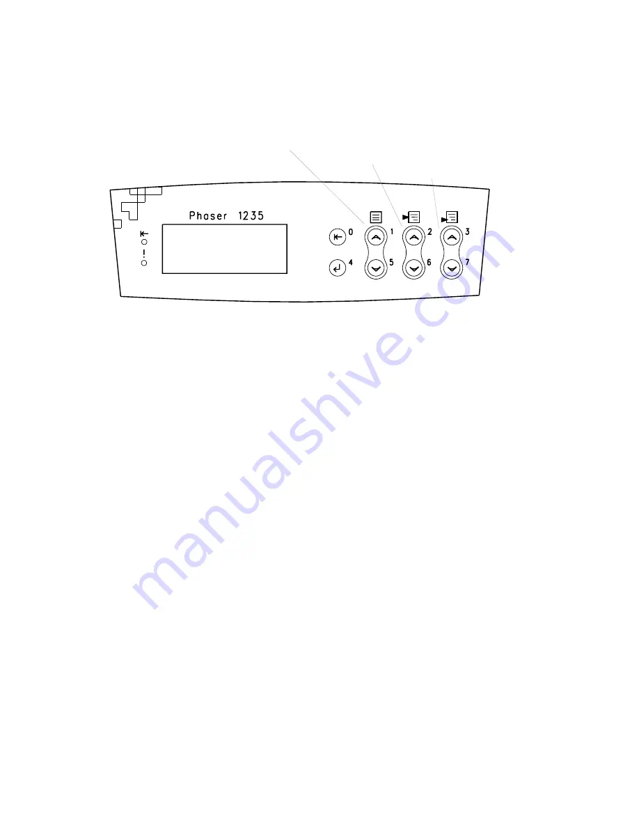
The control panel
The control panel consists of eight labeled keys. These keys navigate the menu system
for printer operations. Two LEDs on the display indicate On Line and active faults.
The LCD display is two lines by twenty-four characters wide.
Key 0 places the printer off-line or on-line. Key 4 is an Enter key. The pairs of keys 1
and 5 are used to scroll through the main menu. Keys 2 and 6 navigate the sub menus,
and Keys 3 and 7 scroll sub-menu values.
On Line LED
Green in color, this LED indicates when the printer is “On Line” and ready to process
data. When transitioning from “On Line” to “Off Line”, the LED flashes at a rate of
two times per second. When data is being received and processed, the LED flashes at
a rate of once per second.
! Fault
Red in color, this LED illuminates whenever operator intervention is required, such as
a paper jam in the printer.
The control panel
Menu up/down
Value up/down
Item up/down
Summary of Contents for 1235DT - Phaser Color Solid Ink Printer
Page 13: ...xiv Phaser 1235 Network Color Printer...
Page 33: ...20 Phaser 1235 Network Color Printer...
Page 77: ...64 Phaser 1235 Network Color Printer...
Page 93: ......
Page 97: ......
Page 99: ......
Page 103: ...90 Phaser 1235 Network Color Printer...
Page 199: ......
Page 202: ...Service Guide 189 Figure 1 Cabinet FRUs...
Page 204: ...Service Guide 191 Figure 2 Top cover FRUs...
Page 206: ...Service Guide 193 Figure 3 Printer chassis FRUs 1 of 2...
Page 208: ...Service Guide 195 Figure 4 Printer chassis FRUs 2 of 2...
Page 210: ...Service Guide 197 Figure 5 Paper tray FRUs...
Page 212: ...Service Guide 199 Figure 6 Paper tray guide FRUs...
Page 214: ...Service Guide 201 Figure 7 Multi sheet bypass feeder FRUs...
Page 216: ...Service Guide 203 Figure 8 Electrical components FRUs...
Page 217: ...204 Phaser 1235 Network...
Page 218: ...Service Guide 205 Figure 9 Duplexer unit...
Page 220: ...Service Guide 207 Figure 10 LowerTray Assembly FRUs...
Page 228: ...Service Guide 215 Wiring Diagram Wiring diagram part 1 of 3...
Page 229: ...216 Phaser 1235 Network Color Printer Wiring diagram part 2 of 3...
Page 230: ...Service Guide 217 Wiring diagram part 3 of 3...
Page 232: ...Service Guide 219 Wire routing at the top of the engine controller board Tie wrap...
Page 233: ...220 Phaser 1235 Network Color Printer Detail of wiring passthru...
Page 235: ...222 Phaser 1235 Network Color Printer...
Page 236: ...NOTES...
Page 237: ...NOTES...
Page 238: ...NOTES...
Page 239: ...NOTES...


