background image


1.3 

 Product Details 


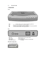
 Product Outfit 


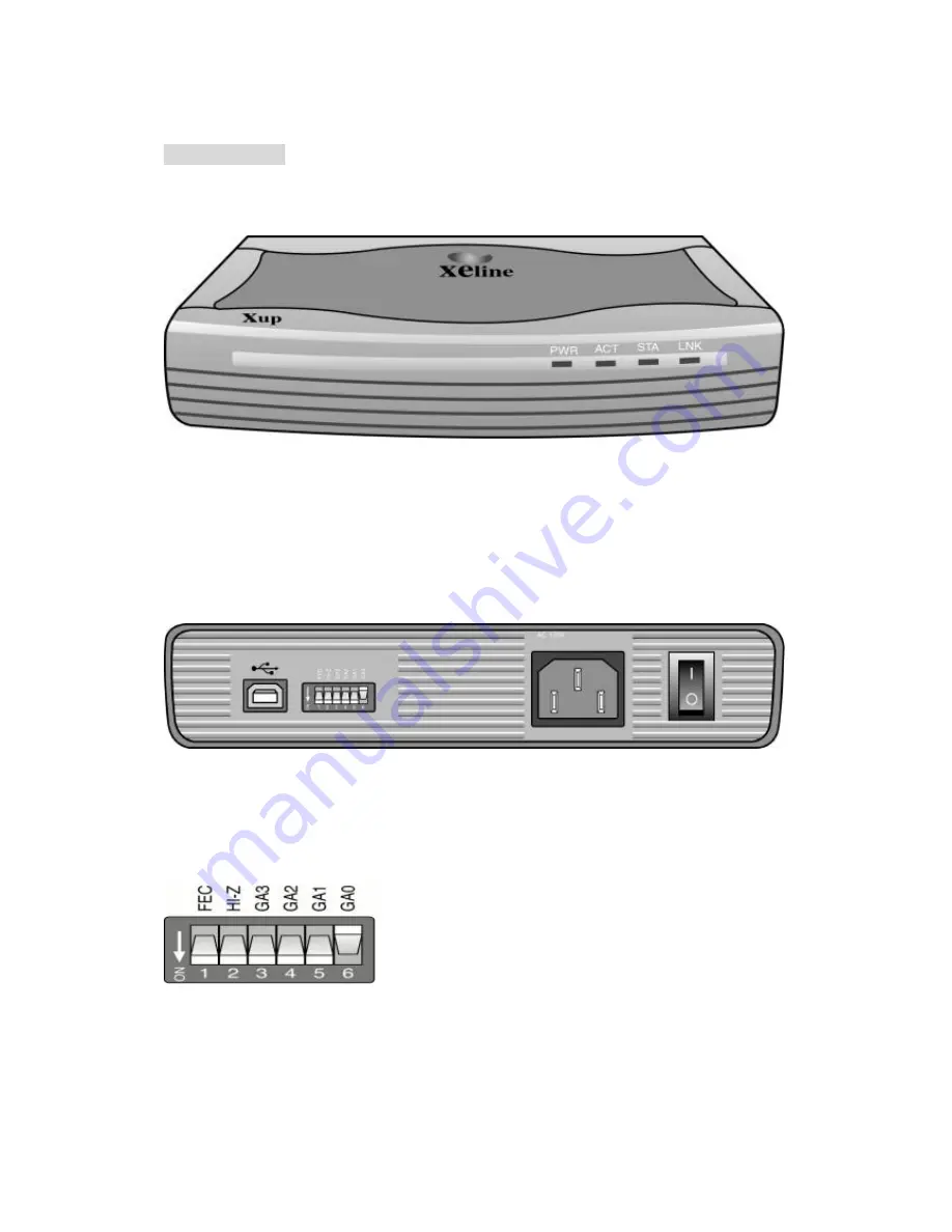
Front 


 PWR   


Turned on when power is connected and power switch is on. 

 ACT   

Blinks when communication is in normal operation. 

 STA 

Turned on when power is connected, and initialization is properly completed.   

 LNK   

Turned on when connection to PC is properly done. 


Rear 


 Power Inlet 


Connection point to connect power cable. 

 Power switch  


To turn on/off the Xup. 

 USB Interface  


Interface between PC and Xup for communication. 

 Performance Selection   


DIP Switch 


DIP Switch Configuration   


Summary of Contents for Xup XM100-01-U

Page 1: ...Xup XM100 01 U User s Manual Xeline Co Ltd...

Page 2: ...erence on actual installation and operation of product from this User s manual Should you have any questions or comments on t his User s manual please communicate through Contact us menu at our web si...

Page 3: ...t Contents 4 1 3 Product Details 5 Product Outfit 5 Specifications 6 2 Installation Guide 7 2 1 Installation 7 Set up Xup XM100 01 U 7 Installation of Xup XM100 01 U Driver 8 TCP IP setting 11 3 Usefu...

Page 4: ...wer lines at home or small office therefore no additional cost is incurred for additional wiring Xup brings networking solution with ease of installation and no special networking configuration work I...

Page 5: ...ation STA Turned on when power is connected and initialization is properly completed LNK Turned on when connection to PC is properly done Rear Power Inlet Connection point to connect power cable Power...

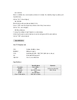
Page 6: ...of Xup Products in communications All the Xup Products in communications should be configured with the same address Set as 0001 when shipped Specifications User PC Requirements CPU Pentium 166MHz or...

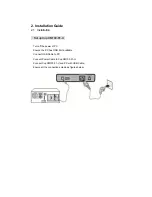
Page 7: ...et up Xup XM100 01 U Turn off the power of PC Ensure the PC has USB Port available Connect USB Cable to PC Connect Power Cable to Xup XM100 01 U Connect Xup XM100 01 U and PC with USB Cable Ensure all...

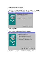
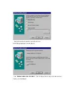
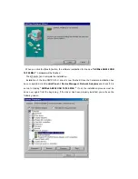
Page 8: ...new device and display the ADMtek 10 100 USB MAC window to install the hardware device driver Based on Windows98 Continue and click Next The Add New Hardware Wizard will search for the driver Click N...

Page 9: ...cify the location to install the control device driver Select Floppy disk drives and click Next Find ADMtek AN986 US B 10 100 MAC from the floppy disk to bring up the above screen Continue and click N...

Page 10: ...llation of the Xup XM100 01 U driver is now finished Once the hardware installation has been completed click Control Panel Device Manager Network Adapters and check if it is set up to display ADMtek A...

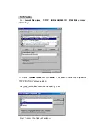
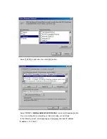
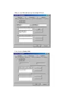
Page 11: ...N 986 USB 10 100 MAC and adjust TCP IP Settings If TCP IP ADMtek AN 986 USB 10 100 MAC is not shown in the network components TCP IP PROTOCOL should be added Click Add button then you will see the fol...

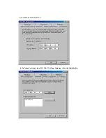
Page 12: ...utton Select TCP IP ADMtek AN986 USB 10 100 MAC and click Properties button If you are setting Home networking or Internet sharing set as follows In the following screen select Specify an IP address a...

Page 13: ...Subnet Mask 255 255 255 0 In the following screen input 192 168 0 1 at New Gateway then click Add button...

Page 14: ...When you use DNS already keep the existing DNS as is If not check on Disable DNS...

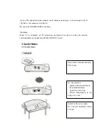
Page 15: ...booted all PC networking environment for users to enjoy the network communications over power line with Xup XM100 01 U is set 3 Useful Notes 3 1 Useful notes Cautions Read User s manual carefully befo...

Page 16: ...15 of the FCC Rules These limits are designed to provide reasonable protection against harmful interference in a residential Installation This equipment generates uses and can radiate radio frequency...

Reviews: