6
2.0 INSTALLATION
©2000 Xantrex Technology Inc.
Pre-installation
NOTE: Before installing the inverter/charger, read all instructions and cautionary markings located in
this manual.
NOTE: The inverter/charger can weigh up to 45 lb. (20.4 kg) depending upon configuration. Always
use proper lifting techniques during installation to prevent personal injury.
Location
Inverters contain sophisticated electronic components and should be located in a well
protected, dry environment away from sources of fluctuating or extreme temperatures and
moisture. Exposure to saltwater is particularly destructive and potentially hazardous.
NOTE: If the inverter is installed in a location where it is exposed to a corrosive or condensing
environment, and fails due to corrosion, it will not be covered under warranty.
Locate the inverter as close to the batteries as possible in order to keep the battery cable
length short. However, do not locate the inverter above the batteries or in the same
compartment as vented batteries. Batteries generate hydrogen sulfide gas which is corrosive
to electronic equipment. They also generate hydrogen and oxygen. If accumulated, an arc
caused by connecting the battery cables or switching a relay could ignite this mixture.
Mounting the inverter in a ventilated enclosure with sealed batteries is acceptable.
NOTE: Inverters can generate RFI (Radio Frequency Interference). Locate any sensitive electronic
equipment susceptible to RFI as far away from the inverter as possible. This includes radios and
TVs.
Mounting
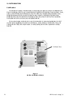
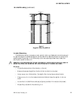
UL Standard 1741 requires the inverter be mounted on a vertical surface (or wall). The
keyhole slots must not be used as the only method of mounting. The purpose of the wall
mounting requirement is to orient the inverter so that its bottom cover, which has no holes,
will not allow burning material to be ejected in the event of an internal fire. Use 0.25 inch
diameter bolts for mounting. The mounting surface must be capable of supporting twice the
weight of the inverter to comply with UL 1741.
Ventilation
Install the inverter in a well ventilated area/enclosure for proper operation. The inverters
thermal shutdown point will be reached sooner than normal in a poorly ventilated
environment, resulting in reduced peak power output and surge capability, as well as shorter
inverter life.
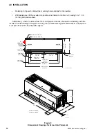
The inverter contains an internal fan. Ensure the air vents and intakes are not obstructed in
any way. Provide a minimum clearance of 1-1/2 inches around the top and sides of the
inverter for ventilation.
Summary of Contents for Trace DR Series
Page 1: ...Installation Operator s Manual DR Series Inverter Charger ...
Page 2: ......
Page 81: ......
Page 82: ......
Page 83: ......


