


4
Smart Pad
3
BASIC CONFIGURATIONS & PROGRAMMING
Now that we have a conceptual understanding of the basic
SmartPad
3
system, let's dive right in and create
three basic module and button configurations and apply the applicable programming.
A Two Gang Configuration
Suppose a client wants to control an AM/FM stereo system from a remote room with one 2-gang keypad
and that he has the following equipment and system requirements:
1. An AM/FM receiver and 4 sources:
TUNER
(AM/FM), two
CD
changers and a cassette
TAPE
deck.
2. When a source button is pressed, the Smart Pad must turn on the AM/FM receiver and the associated
source.
3. The keypad must have the following control function commands for each source:
TUNER:
Tuner Up/Down (scroll of preset stations), AM/FM (select).
CD 1 and CD 2
: Play, Scan Forward/Reverse, Track Forward/Reverse, Disk+, Disk– (select), Pause,
Stop.
TAPE
: Play Forward, Play Reverse, Fast Forward, Rewind, Pause, Stop.
4. Speakers in the remote room must be mutable by using the
relay
in the
SmartPad
3.
This is the basic client specification for this application of the
SmartPad
3.
The next step is to determine what
SmartPad
3
modules
and keypad
buttons
are required to perform this
job, as follows:
1. Since there are 4
sources
, 4 banks will be required. We will need the
KM4
for the first Key Module.
2. Since there are a good number of control
functions
to perform, we will need the
KM1F
for the second
Key Module.
3. Now, since this is a 2-gang configuration, we need a
PM110
Base Module into which we plug the
KM1F
and the
KM4
.
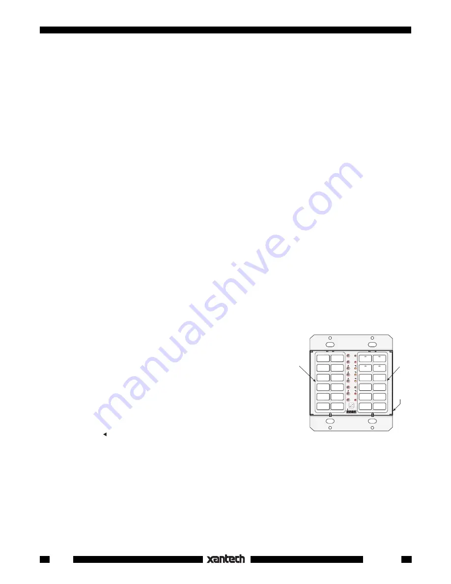
Fig. 1
shows the basic configuration.
Fig. 1
Two Gang Configuration
CLR MEM
RESTORE
NETWORK
PGM
TRNS
XFER
ERR
CNCL
FULL
DEL
EDIT
DELAY
SEQ
IR
STEP
C
O
M
B A 9 8 7 6
5
4
3
2
1
0
F
E
D
C
PROTECT
WRITE
NETWORK
ADDRESS
PM110
KM1F
KM4
4. The next step is to determine exactly what
buttons
are required
to carry out the control functions needed.
5. We begin this process by assigning the
Source
buttons first;
CD1,
TUNER
,
CD2
and
TAPE
. See
Fig. 2
.
6. Next, we assign the
function
control buttons based on the list of
functions given on page 7.
NOTE:
Most of the buttons for steps 5 and 6 are available in the
SOURCE
bag of buttons supplied with the
KM4
and in the
FUNCTION
bag of buttons supplied with the
KM1F
. Buttons
CD1,
OFF
,
RAN-
DOM
,
A/B, *
and (reverse play) are not supplied but are available
separately from Xantech. They are listed in the dealer price list (along
with all buttons currently available for the
SmartPad
3
system). They should be ordered at the same time as
the other keypad parts.
7. Now that all the buttons have been assigned (as shown in
Fig. 2
), it is necessary to insert them into
the
KM1F
and the
KM4
module shells. Then insert the completed key modules into the
PM110
. See
page 18 for Button and Module Assembly instructions.
NOTE:
In this example, the button and module positions are placed in what is considered an ergonomically
pleasing arrangement. You may, however, place the buttons in any arrangement you wish, to best fit taste
and application.


