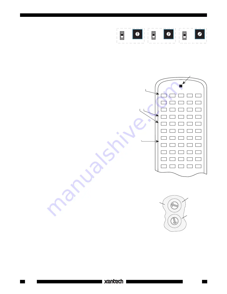
background image

20

Smart Pad

3

Fig. 22

RC68+ With Overlay 

I

 for

Relay Mute Programming.
(RC68 works also, but the 

I

ON/TOG

OFF

0

ON/TOG

OFF

1

ON/TOG

OFF

2

ON/TOG

OFF

3

ON/TOG

OFF

4

ON/TOG

OFF

5

ON/TOG

OFF

6

ON/TOG

OFF

7

ON/TOG

OFF

8

ON/TOG

OFF

9

ON/TOG

OFF

A

ON/TOG

OFF

B

ON/TOG

OFF

C

ON/TOG

OFF

D

ON/TOG

OFF

E

ON/TOG

OFF

F

I

#

0

 ON/ TOG Button

with Code Group 

FA

initiates Relay Mute
Coding Procedure.
(Step 5)

These numbers,

0~F

, represent

16 addresses 

0~F

on SmartPad3's.

Use 

I

 Overlay

There is an

ON

/

TOG

 and

an 

OFF

IR command
assigned for
each address.
Code Group

D8

 (default).

RC68

(rear

panel)

0 1 2

3

4

5

6

78

9A

B

C

D

E

F

0 1 2

3

4

5

6

78

9A

B

C

D

E

F

1st Digit

(Left on
RC68+,

Upper on

RC68)

2nd Digit

(Right on

RC68+,

Lower on

RC68)

Fig. 23
D8

 Default

Code Group
Setting for
SmartPad

3

7. Within 3 seconds, press the button on the

SmartPad

3

 where you want Relay 

Mute ON

 (i.e.

a MUTE ON button.  See 

Fig. 24

). The active

Source

 button LED 

will flash twice

 to confirm

your action.

8. Again, within 3 seconds, press the button on the

SmartPad

3

 where you want Relay 

Mute OFF

(i.e. a MUTE OFF button).  The active 

Source

button LED 

will flash twice

 to confirm your

action followed by 

four flashes

 to indicate the

end of Relay Mute programming for 

Address 0

.

The 1st SmartPad

has now been coded to respond to

the 

MUTE


ON

 and 

MUTE OFF

 buttons (pair) you

selected on the SmartPad

3

.

It will 

also

 respond, over the IR network, to the #

0 ON/

TOG

 and 

OFF

 IR commands from the RC68+ (or

RC68) set to the default Code Group 

D8

.  Refer to

Figs. 22

 & 

23

.

9. Test the IR commands by setting the rear

switches on the RC68 to 

D8

 (the factory default

Code Group setting for the SmartPad

3

).

10. Pressing the #

0 ON/TOG

 IR command on the

RC68 should cause the Relay to 

MUTE ON

 (if

OFF).  Pressing the #

0 OFF

 button should cause

the Relay to 

MUTE OFF

 (if ON).  Refer to 

Fig. 22

.

Programming the remaining SmartPad

3

's

Each remaining keypad will need to respond to unique
muting commands, otherwise muting one room on the
IR network with the RC68 IR commands, will mute all
the rest as well.

Since any PM110 can store unique coding for up to 16
addresses, we will use the 1st keypad to program
codes for the rest, as follows:

11. On the 1st keypad (PM110), change the 

NET-

WORK ADDRESS

 switch to match an address

of the next keypad in the system (i.e., 

1

) then

press 

RESTORE

 on the 1st keypad.

12. Repeat steps 4 through 8.

13. Repeat steps 11 and 12 for each of the remain-

ing addresses you have for the rest of the Smart
Pad

3

's.

B A 9 8 7 6

5

4

3

2

1

0

F

E

D

C

KEYPAD #1

(PM110)

Address  0

KEYPAD #2

(PM110 or LM110)

Address  1

KEYPAD #3, etc.

(PM110 or LM110)

Address  2, etc.

B A 9 8 7 6

5

4

3

2

1

0

F

E

D

C

B A 9 8 7 6

5

4

3

2

1

0

F

E

D

C

PROTECT

WRITE

PROTECT

WRITE

PROTECT

WRITE

NETWORK

ADDRESS

NETWORK

ADDRESS

NETWORK

ADDRESS

Fig. 21

Set Each Keypad to a Unique Network Address

IMPORTANT

: You 

must

 press 

RESTORE

 each time you change the 

NETWORK ADDRESS

 in step

11.

At this point the coding that causes each keypad to respond to its own mute buttons and to the unique RC68
commands over the IR Network, for each keypad address, is stored in the 1st keypad. To transfer this coding
to the rest of the keypads, do a Network Transfer as follows:

14. Set the 

WRITE PROTECT

 switch to the 

WRITE

 position and press 

RESTORE

 on all keypads.

Summary of Contents for SMRTP3

Page 1: ...markings are included with each key module Many specialized versions are also separately available from Xantech Pre labeled buttons do not require any tedious insertion of small icon key caps Up to 8...

Page 2: ...have 12 buttons The last four have 11 buttons and include a cursor key cluster The module shells and buttons are available in white ivory and black An illustration and description of each follow KM1F...

Page 3: ...system into which the Key Modules are docked They contain the electronics for programming memory except the EM110 and include flanges for J box mounting An illustration and description of each follow...

Page 4: ...for the second Key Module 3 Now since this is a 2 gang configuration we need a PM110 Base Module into which we plug theKM1F and the KM4 Fig 1 shows the basic configuration Fig 1 Two Gang Configuratio...

Page 5: ...d commands and the Switched AC Outlet on the AM FM receiver Refer to Fig 3 We ll begin by teaching commands to the 4 source bank buttons TO EM110 L L R R SPEAKER OUTPUT L L R R AMPLIFIER INPUT 12V IR...

Page 6: ...d remote at the IR window and press it s play button 5 When the code is learned the PGM LED will flash again indicating it is ready to learn a command at another button 6 Press reverse scan button The...

Page 7: ...owing equipment and system requirements 1 An AM FM receiver and 4 sources TUNER AM FM two CD changers and a cassette TAPE deck 2 When a source button is pressed it must turn the AM FM receiver ON alon...

Page 8: ...tions in order for the source indicators and bank selections to operate 7 The keypad is now ready to be wired into the total system See Fig 6 Power may then be applied and we can proceed with the Prog...

Page 9: ...de is learned the SEQ LED will flash then go steady when you release the key on the remote 14 Press CNCL two times to exit the programming tier mode You can now test these learned commands But first b...

Page 10: ...changer an LD Laser Disc player a cassette TAPE deck a SAT Satellite receiver and a VCR 2 When a source button is pressed it must turn on the AM FM receiver and the associated source 3 The keypad mus...

Page 11: ...ly so that they can be custom configured with the desired button arrangements To assemble disassemble change and reassemble as desired proceed as follows Assembly Fig 11 Typical Key Module Assembly Ru...

Page 12: ...push hold tiering and sequence commands on any key Commands storable into 1 to 8 banks selectable by bank keys Editing of command sequences Intelligent Power Management inhibits first command in a seq...

Page 13: ...rols for programming only It will not repeat commands through the network system 13 COM Port RS232 signal compatible port for uploading or downloading to from a computer or transferring programmed con...

Page 14: ...e keypad defaults to bank 1 top left source button after each power up The unit is now ready for programming communications with a PC or cloning of programmed contents from one keypad to another Learn...

Page 15: ...d you want in the sequence 4 When the command has been learned the SEQ and PGM LEDs begin flashing and continue to flash until you release the key on the remote 5 The SEQ LED will then turn on steady...

Page 16: ...e button in a 2 step sequence This permits sources to be selected after zone turn on They would otherwise be blocked when zone turn on drives the STATUS line high Tiering The SmartPad3 has the ability...

Page 17: ...he keypad and have pressed CNCL to leave the programming modes you may send them to the controlled equipment simply by pressing the key that relates to them It is recommended that you test each set of...

Page 18: ...ED will come on steady 8 Input the IR command in the normal manner 9 When stored the PGM and SEQ LED will flash then go out You may now STEP to the next command NOTE You do not have to delete anything...

Page 19: ...ystem STATUS Voltage 12VDC 12 VDC GND STATUS IR IN EMITTERS IR RCVR 789 44 CONNECTING BLOCK Fig 20 Network Connection Diagram Programming for the Speaker Relay The relay will respond to commands for M...

Page 20: ...23 9 Test the IR commands by setting the rear switches on the RC68 to D8 the factory default Code Group setting for the SmartPad3 10 Pressing the 0 ON TOG IR command on the RC68 should cause the Relay...

Page 21: ...le TOGGLE command for instance would work well under the MUTE button in a system such as that in Figs 5 6 To program Toggle only proceed as follows 19 Begin by following steps 1 through 7 20 At this p...

Page 22: ...ressing D8 in the above process or by doing a CLR MEM Fig 15 Be aware that CLR MEM will erase all user programming Bank Tracking Programming Each Source bank key of the SmartPad3 can be programmed to...

Page 23: ...e 90 from the RC68 into the TUNER bank of the 1 keypad To do this follow the previous procedure steps 1 through 8 Now pressing CD or TUNER on either keypad will result in them tracking together Comman...

Page 24: ...y refer to Fig 31 To perform a Network Transfer proceed as follows 1 Connect up to 16 keypads onto a common IR bus network Refer to Fig 31 Be sure the system is powered up 2 If you have not already do...

Page 25: ...witch to the PROTECT position on all keypads to prevent unintended alteration or erasure Cloning Transfer Time The time it takes to complete a cloning process depends on the amount of data required fo...

Page 26: ...other wall mounted decorator style components A few things to keep in mind are as follows NETWORK RESTORE COM PORT B A9876 5 4 3 2 1 0 F E D C NETWORK ADDRESS WRITE PROTECT WRITE READ 1 3 4 LM110 1 1...

Page 27: ...er does not output IR commands Corrupted data in the 2nd keypad may have prevented a proper data transfer a Press the CLR MEM button twice on the 2nd keypad b Repeat the Command Transfers Cloning proc...

Page 28: ...signal output current 100 milliamps STATUS Terminal Power Management Turn on Voltage 5 to 30 volts DC 8mA 12V DC COM Port RS232 Signal Compatible Speaker Relay Stereo Speaker Pair Muting Contact Ratin...

Reviews: