XJ128 and XJ128 Plus Printhead
XJ128 Guide to Operation
Xaar Document no: D031010302 Version A
Page 26
A suitable connector that could be used on a printhead interface cable is the corresponding
”
male
”
connector for vertical mounting:
“
AMP
™
30 pin plug/post board
-to-board connector
”
. The AMP
™
part
number for a suitable printhead interface flex-cable connector is 9-176140-0 (male).
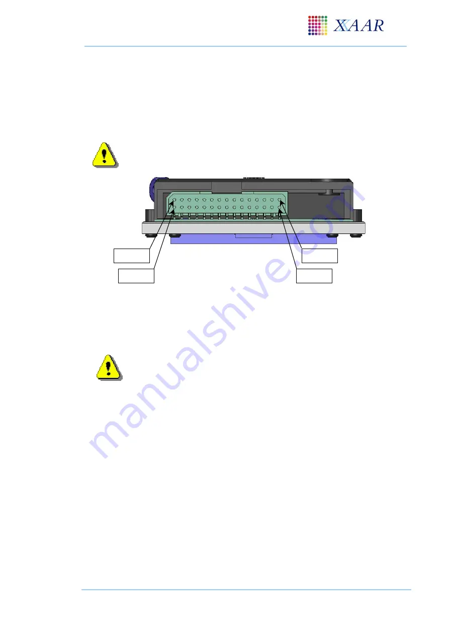
The chamfer in the upper left-hand corner of the connector, (when the printhead is viewed from the
rear) indicates Pin 1.
Typically, the AMP
™
connector is fixed to a 30
-way flex-cable. A rigid connection
is not advised as this exerts stress onto the surface mount AMP
™
connector.
Fig 5.2
–
Pin numbering on the printhead electrical connector
5.5 Grounding and isolation
Please note that the following points should be addressed when interfacing with the
XJ128 printhead. If a Switched mode power supply is used, ensure it is adequately
screened. By default, use screened cables. Filter the mains input to the power supply.
Use a short, thick connection, from the incoming earth of the mains supply direct to
the chassis of the printing system.
GND, GNDL and GNDH (ground supplies) should be made via the ground of the 30-pin printhead
connector. No electrical connection should be made from the 30-pin printhead connector to the
chassis of the printhead. GNDL and GNDH should be a common ground, and are joined within the
printhead. The low voltage ground (GND), and the high voltage grounds (GNDL and GNDH) must
not be joined or grounded at any other point. Refer to section 6.3.1 for detail on grounding schemes.
Pin 1
Pin 2
Pin 30
Pin 29


