3600W Digital Inverter with Pure Sine Wave
AFTER SALES SUPPORT
e-mail: [email protected]
1800 909 909
MODEL: №. INF3800A-1 • 03/2018 • 59905
(toll free)
AFTER SALES SUPPORT
(toll free)
3600W Digital Inverter with Pure Sine Wave
e-mail: [email protected]
1800 909 909
MODEL: №. INF3800A-1 • 03/2018 • 59905
18
19
Indicators
General Assembly
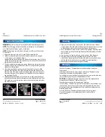
This generator has three main LED indicators to indicate to the operator
various conditions as follows:
1. Low oil indicator (Fig L)
The low oil indicator light (7) is a yellow LED and will illuminate when the oil
level of the generator is too low. The generator will stop operating within 10
seconds if the yellow light comes on.
The yellow LED will illuminate when
the generator is being attempted to
start if the oil is low, i.e. when the cord
is being pulled, the yellow LED will
glow if there is insufficient oil. In this
condition, the generator will not start.
In this condition you need to add oil
for the generator to operate.
2. Load Status indicator (Fig M)
The red load status indicator light (8) advises the operator that a fault
has been detected and the power supply to the control panel has been
interrupted. When the red load status indicator is operating red, there is NO
240Va.c. available to the control panel.
When the engine is running the load status indicator light (8) flashes under
the following conditions:
a. Flashing once indicates low voltage protection, caused by the engine
rotation speed not meeting the specified reqauirements.
b. Flashing twice indicates the engine is overheated, caused by high
temperature.
c. Flashing 3 times indicates overload
protection caused by an excessive
electrical overload.
d. Flashing 4 times indicates there is
an electrical problem most likely
caused by a short circuit.
L.
M.
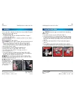
Following assembly of the wheels, it is
recommended to assemble the additional wheel
foot (3) for stability and to keep the generator on a
level surface.
1. Raise the opposite end of the generator that the
wheels have been assembled on by placing a
wooden block (or something similar) underneath
the bracket that the feet have been assembled on
(Fig B).
2. Insert the supplied hex head screw through the
bottom of the foot so it comes out the opposite
side (Fig H).
Using the supplied 10mm tube spanner (30), insert
into the foot and engage the head on the hex
head screw. Thread the hex head screw into the
large boss on the base frame cross member on the
handle end of the generator (Fig I). Tighten firmly.
Assembly of the Folding Carry Handle
This generator is supplied with a folding carry handle
(6) to assist with transportation when wheeling the
generator around on the wheels.
1. Align the holes on each bracket of the carry handle
with the holes on each side of the generator frame
(Fig J).
2. With the handle in position, insert each screw
through the outer bracket of the handle, then
through the holes in the generator frame, and
through to the opposite side of the internal
bracket of the handle.
3. Secure the handle into position by applying the
nyloc nuts onto the screws and securing
finger tight.
Using the supplied double ended screwdriver
(phillips head) (32) to hold the screw, then use the
multi size spanner (33) in a clockwise direction to
secure the nyloc nut in place (Fig K).
H.
J.
K.
I.
Indicators


