Worcester Greensource 6 Installation Manual Download Page 29

INSTALLATION AND SERVICE MENU (I/S)

6 720 641 467 (2010/01)

29

10 INSTALLATION AND SERVICE MENU (I/S)

Fig. 31

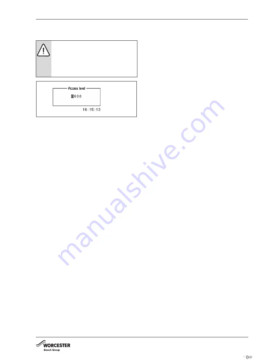
A 4-digit access code is required to open the installation 
and service menu (I/S).
1. Hold down the menu dial for 5 seconds to open 

Advanced menu

.

2.  Select 

Access level

.

3. Enter the 4-digit access code with the menu dial and 

press to confirm your entry. The access code is the 
current date and comprises two digits for the month 
and two for the day (e.g. 0920 for the 20th 
September). The display shows Access = service.

4. Press menu dial to open 

Menu

. The most commonly 

used menu points are accessible at the user level; the 
menu points of the installation and service menu (I/S) 
are only accessible at 

Menu

. Hold down the menu dial 

for 5 seconds to open 

Advanced menu

.

5. In 

Advanced menu

 select point 

Access level

. Enter 

access code 0000 to return to the user level.

120 minutes after the last entry, the control unit returns 
automatically to the user level.

CAUTION: 

Changes in the installation and 

service menu (I/S) can have severe 
consequences for the system.

B

Only qualified contractors should make 
adjustments in the installation and 
service menu (I/S).

6 720 641 467-02.1I

For latest prices and delivery to your door visit MyTub Ltd - www.mytub.co.uk - [email protected] 0844 556 1818   

Summary of Contents for Greensource 6

Page 1: ...TER HEAT PUMP WITH DOMESTIC HOT WATER DISTRIBUTION UNIT GREENSOURCE 6 720 641 467 00 1I 6 KW 7 KW AND 9 5 KW 6 720 641 467 2010 01 For latest prices and delivery to your door visit MyTub Ltd www mytub co uk info mytub co uk 0844 556 1818 ...

Page 2: ...ump to the heating system 18 7 9 Connection principle of the internal unit 19 7 10 Filling the heating system 20 8 Power supply 21 8 1 Accessory 21 8 2 Emergency operation 21 8 3 Heat pump 22 8 4 Internal unit HWDU 151 24 9 Control panel 27 9 1 Control panel display 27 9 2 Control panel function 27 9 3 Menu levels 28 10 Installation and service menu I S 29 11 Menu overview 30 12 Commissioning 33 1...

Page 3: ...een instructed in understands and is aware of the heat pump s operating conditions and effects SERVICE AND MAINTENANCE B Only qualified personnel may carry out repairs Incorrect repairs can lead to serious risks to the user and may invalidate your warranty B Only use original Bosch spare parts B Service and maintenance must be carried out annually by an suitably qualified service representative Sa...

Page 4: ...e appropriate Building Regulations The Benchmark Checklist can be used to demonstrate compliance with Building Regulations and should be provided to the customer for future reference Installers are required to carry out installation commissioning and servicing work in accordance with the Benchmark Code of Practice which is available from the Heating and Hotwater Industry Council who manage and pro...

Page 5: ...y and Welfare Regulations 1996 The Construction Design and Management Regulations 1994 The Lifting Operations and Lifting Equipment Regulations 1998 Where no specific instruction is given reference should be made to the relevant codes of Practice Potable water All seals joints compounds including flux and solder and components used as part of the secondary domestic water system must be approved fo...

Page 6: ... Room sensor T5 with cable with HWDU 7 Flexible connection hose With unvented air to water kit 8 Blending valve 9 DHW expansion vessel 10 High flow rate inlet control set 11 Expansion vessel hose 12 Acetal tundish 13 Wall mounting kit for expansion vessel 14 Waste coupler 15 Filling loop with valve 6 720 641 467 79 1I 4 5 6 3 2 8 10 1 7 9 12 11 14 13 15 For latest prices and delivery to your door ...

Page 7: ...eat only The maximum operating flow temperature is factory set to 62 C This can be changed by the installer to a maximum of 70 C It is recommend that the factory supplied blending valve be fitted in line with G3 regulations Minimum operating temperature The heat pump stops when the outside temperature is below 20 C Only the internal unit will then generate heat The heat pump restarts automatically...

Page 8: ...all required settings at the control panel 13 Check the heating installation after commissioning and insulate all external pipe work 5 7 LOCATIONS OF THE TEMPERATURE SENSORS 5 7 1 GREENSOURCE 6 9 5 WITH INTERNAL UNIT HWDU 151 Fig 3 Greensource 6 9 5 internal unit HWDU 151 T1 Flow temperature sensor T2 Outside temperature sensor T3 Cylinder temperature sensor T5 Room temperature sensor T6 Hot gas t...

Page 9: ...he external CAN BUS cables when routed into the hwdu are not in connect with the mains cable The connection between the circuit boards is by four wires because the 12V supply between the circuit boards must also be connected The circuit boards have markings for both the 12V and CAN BUS connections Fig 4 Switch S1 highlights the beginning and end of the CAN BUS cable This means that the CPU board i...

Page 10: ... bands etc should always be used if available If not available the following handling precautions must be observed touch the boiler earth immediately prior to removing the part from the packaging Handle the PCB only at the edges Touch earth on a regular basis whilst the board is being fitted and connected Do not touch any electronic components A condition for good ESD protection is a ground connec...

Page 11: ...ay 3 Capacitor 4 Soft starter 5 PCB IOB board 5 10 2 INTERNAL UNIT HWDU 151 Fig 9 Connection chamber internal unit 1 Pressure gauge System operating pressure 0 5 1 5 bar 2 Mixing valve 3 Heat carrier pump G2 4 Pump for heating system G1 5 Heating three way valve 6 Hot water three way valve 7 Drain point 6 720 616 818 08 1I 1 3 2 7 6 5 4 9 8 6 720 641 467 70 1I 1 2 3 4 5 3 4 1 6 720 641 935 05 1I 2...

Page 12: ...ad REQUIRED MINIMUM CLEARANCES FOR THE HEAT PUMP A minimum clearance of 1 m is required in front of the pump the minimum clearance to the back and sides is 0 3 m If a roof is installed it must be positioned at least 1 5m above the heat pump to avoid the recirculation of cold 818 839 1223 665 60 50 643 78 147 178 92 217 408 3 4 2 1 6 720 616 817 27 1I For latest prices and delivery to your door vis...

Page 13: ...d water supply to the outlet marked cold water B Connect the DHW pipe to the outlet marked DHW The following connections must be made at the heat pump B A 32 mm drain pipe from the drain connection to the drain Installation of the valve with filter B Install the valve with filter horizontally in the return to the heat pump and as near to the heat pump as possible Between the heat pump and the hous...

Page 14: ...VE The task of the particle filter is to filter out dirt before it can enter the heat pump Accordingly the supplied filter valve must always be fitted on the return pipe between the HWDU and the outdoor heat pump It should be fitted as close to the heat pump as possible and be horizontal 347 1 2 3 4 103 152 194 300 420 543 30 558 6 720 616 817 06 1I For latest prices and delivery to your door visi...

Page 15: ...ld be sought 7 3 DETAILED G3 DISCHARGE PIPE INSTALLATION REQUIREMENTS The discharge pipework must be routed in accordance with part G3 of schedule 1 of the building Regulations The tundish should be vertical located in the same space as the unvented hot water cylinder and be as close as possible and within 600mm of the safety device e g the temperature relief valve The discharge pipe from the tund...

Page 16: ...rked example 5 Fixed grating 6 Trapped gulley 7 Discharge below fixed grating 3 9d gives alternative points of discharge 7 4 TUNDISH HWDU Fit the tundish and straight fitting G1 x 28 mm as shown on the illustration The tundish and fitting are supplied together with the HWDU as part of the G3 regulations Fig 16 1 Tundish 6 720 641 467 75 1I 7 1 2 4 3 5 6 600 mm maximum 300 mm maximum 6 720 641 467 ...

Page 17: ...f corrosion products in the form of magnetite and deposits Magnetite has a grinding effect on the heating system s pumps valves and components with turbulent flows such as the condenser Heating systems which require regular filling or where the heating water is not clear when drained require remedial measures before the installation of a heat pump for example the heating system must be fitted with...

Page 18: ...Install the flexible hoses at the inlet and outlet for the heat pump supplied as standard For the connection between the internal unit and the heat pump up to 20 m length with a 28 mm diameter such as Microflex or Ecoflex B Outdoor pipes must be insulated with a material that cannot absorb moisture such as Armaflex class 0 PUMP CURVES Fig 18 Heating circuit pump 2000 1500 1000 500 0 l h 0 10 20 30...

Page 19: ...ump stops automatically and can no longer heat DHW Under those conditions the additional electric heater in the internal unit automatically takes over the DHW heating Fig 19 Internal unit Q46 E10 Radiator system C11 Expansion vessel C12 Primary water storage tank G1A Heating system pump G1B Heating system pump P11 Pressure gauge Q10 Mixing valve Q12 Isolating valve Q13 Water outlet E20 Heating sys...

Page 20: ...ng system 4 Also vent via the heat pump air vent valve 5 Fill the heating system up to the correct pressure The standard pressure is 1 2 bar 6 Shut the heating water filling cock when the correct pressure is reached Fig 20 Connection chamber internal unit 1 Pressure gauge 0 5 1 5 bar Fig 21 Heat pump 1 Air vent valve WARNING The water heater can crack if filling is performed in the wrong order B F...

Page 21: ... generation is taken over by the electric additional heat if the control unit experiences a fault See the operating instructions for further information regarding emergency mode On the IOB board there is a thermostat for regulating the flow temperature in emergency mode At the factory the thermostat is set to 35 C This standard setting applies to systems with underfloor heating If a house is exclu...

Page 22: ...sure switch LP Low pressure switch S1 Termination switch T6 Hot gas temperature sensor T8 Heating water temperature sensor out T9 Heating water temperature sensor in T10 Condenser temperature sensor T11 Refrigerant temperature sensor evaporator T12 Air temperature sensor evaporator 1 Compressor type function jumper 2 Contact 3 Internal unit HWDU 151 1 2 6 720 641 467 73 1I 1 3 For latest prices an...

Page 23: ...ned communication cable between the internal unit and the heat pump to terminals GND CANL CANH and 12V Æ chapter 5 8 6 720 641 467 84 1I CAUTION Do not mix up the 12V and CAN BUS connections The processors are destroyed if 12V is connected to the CAN BUS B Check that the four cables are connected to the contacts with the corresponding marking on the circuit board For latest prices and delivery to ...

Page 24: ...1 Termination switch S2 Emergency switch T Thermostat for emergency operation T1 Flow temperature sensor heating T2 Outside temperature sensor T3 Cylinder temperature sensor T5 Room temperature sensor accessory T99 Temperature sensor for emergency operation 1 Function jumper 2 Contact 3 Power guard accessory 4 Connect the power transformers to the incoming power supply 5 Heating water outlet towar...

Page 25: ...Outside temperature sensor T5 Room temperature sensor accessory 1 Internal unit 2 Power guard accessory 3 Heat pump 4 Transformer for the voltage supplied by the large control panel 5 Safety switch 6 Fuse Greensource 6 16A Greensource 7 25A Greensource 9 5 25A 7 Fuse HWDU 151 25A 1 6 720 641 467 78 1I 2 3 4 5 6 7 For latest prices and delivery to your door visit MyTub Ltd www mytub co uk info mytu...

Page 26: ...the temperature via a room temperature sensor accessory connect the sensor to terminals Ai4 and GND CAN BUS Connect the screened communication cable between the internal unit and the heat pump to terminals GND CANL CANH and 12V Æ chapter 5 8 6 720 614 056 21 1D CAUTION Do not mix up the 12V and CAN BUS connections The processors are destroyed if 12V is connected to the CAN BUS B Check that the fou...

Page 27: ...button is used to start and switch off the heating installation MENU DISPLAY Fig 29 9 2 CONTROL PANEL FUNCTION The menu dial is used to navigate the menus B Turn the menu dial anti clockwise to scroll down through the menus B Turn the menu dial clockwise to scroll up through the menus B Press the menu dial to confirm the selection when the desired row is marked At the top and bottom of each sub me...

Page 28: ...r functions Installer Service Basic settings for installers or service representatives The system user only sees the menu points shown on both user levels See the operating instructions for a description of these two user levels For latest prices and delivery to your door visit MyTub Ltd www mytub co uk info mytub co uk 0844 556 1818 ...

Page 29: ... open Menu The most commonly used menu points are accessible at the user level the menu points of the installation and service menu I S are only accessible at Menu Hold down the menu dial for 5 seconds to open Advanced menu 5 In Advanced menu select point Access level Enter access code 0000 to return to the user level 120 minutes after the last entry the control unit returns automatically to the u...

Page 30: ...ge I S Correct sensor I S Fan defrost interval I S Fan defrost time I S Forced defrost I S Block crankcase heater at high outdoor temperature I S Anti jamming mode time I S Activation time alarm buzzer I S T1 Set point value maximum I S Display I S Electrical connection I S Heat pump size I S Room temperature setting T5 K Temperature increase decrease not T5 K Temperature increase decrease setting...

Page 31: ...ay of Temperatures Inputs Outputs I S Correct temperature sensor I S Defrost settings T12 T11 settings I S Maximum outdoor temperature I S T11 Maximum temperature I S Maximum time I S Delay after compressor start I S Minimum time between defrosts I S Compressor pressure equalisation time I S 4 way valve pressure equalisation time I S Forced defrost I S Heating cable time after defrost I S Fan defr...

Page 32: ...ness K I S Alarm Alarm log K I S Alarm history I S Warning log I S Access level K I S Return to factory settings K I S Deactivate alarm buzzer K Program version K I S Connected I O cards I S Advanced menu Tab 5 For latest prices and delivery to your door visit MyTub Ltd www mytub co uk info mytub co uk 0844 556 1818 ...

Page 33: ...on Start up 12 2 1 CONNECTED EXTRA SENSORS If room temperature sensor T3 or T5 is installed Yes must be displayed underneath menu point T3 acknowledged or T5 acknowledged 12 2 2 AIR WATER PUMP IN OPERATION Internal units can also be commissioned without connected heat pump If no heat pump is connected B Select No 12 2 3 CONNECTION CAPACITY Fig 36 State total output Setting of total connected outpu...

Page 34: ...tive if the value under menu point Fan defrost interval lies between 1 and 10 standard setting 1 With value 1 the fan will be defrosted each time defrost is activated With value 3 the fan will be defrosted every third time defrost is activated Select 0 under Fan defrost interval if you want to disable this function B Select the duration of fan defrost under menu point Fan defrost time Minimum 1 mi...

Page 35: ...B Select the heat pump voltage 230V or 400V 12 2 16 HEAT PUMP SIZE Fig 42 Set the heat pump output For a heat pump output between 6 and 11 kW B Select 6 11kW For an output between 12 and 17 kW B Select 12 17kW 12 2 17 ALARM DURING START UP An alarm may be triggered during start up if a temperature is captured in the condenser that is too low The reason for this is that water has been filled in tha...

Page 36: ...ating curve if it is set higher than 62 C Fig 45 Permitting a higher flow temperature B In the installation and service menu I S select Advanced menu B Select Additional heat settings B Select Electric additional heat settings B Select T3 Stop temperature B Set the required value Factory setting 62 C and maximum 70 C The table of Factory settings Æ Chapter 15 1 shows all functions which can be adj...

Page 37: ...rectly for the pressure drop in the system A recommended temperature difference across the heat pump on the hot side is between 5 10ºC The nominal flows provided in Technical information shows a difference of 7ºC in operating mode 7 45ºC Check this by reading the sensors T9 heat transfer fluid in and T8 heat transfer fluid out When commissioning is carried out at a low outdoor temperature below 0º...

Page 38: ...rature differential is permanently above the set value for defrost To enable defrost the Delay before defrost must also have expired DEFROST Indicates the remaining time until defrost is activated for the evaporator HEATING CABLE Indicates the remaining time until the heater cable in the heat pump drain pipe is activated HEATING MAXIMUM OPERATING TIME AT HOT WATER DEMAND Displays the remaining tim...

Page 39: ...f the menu dial is pushed when Acknowledge is marked the alarm symbol goes out in the menu window and in the alarm log and the warning signal is muted The heat pump starts again within 15 minutes if heating is required The alarm symbol continues to be displayed if a fault is not remedied The ON and fault indicators change from flashing red to constant red indications Every alarm is stored in the f...

Page 40: ... there is never a risk involved in resetting an alarm All the alarms that can appear in the menu display are described in this section The descriptions give an idea about the nature of the alarm and what can be done to rectify it The alarm log see Advanced menu shows the alarms and warnings that have occurred 14 8 1 LIST OF ALL ALARMS Tripped low pressure switch Tripped high pressure switch Failur...

Page 41: ...AIR IN THE HEATING SYSTEM B Select Acknowledge B Check whether air is in the heating system B Fill the heating system and vent if required POSSIBLE CAUSE 2 BLOCKED PARTICLE FILTER B Select Acknowledge B Check filter B Clean filter if required Æchapter 14 7 POSSIBLE CAUSE 3 INADEQUATE FLOW RATE ACROSS THE HEAT PUMP B Select Acknowledge B Check whether the heat pump has stopped Æ Fig 53 on page 41 B...

Page 42: ...rature sensor T8 is fitted inside the heat pump This stops the compressor for safety reasons as soon as the flow temperature exceeds the selected value PROBABLE CAUSE 1 INSUFFICIENT FLOW OVER THE HEAT PUMP B Select Acknowledge B Check whether the primary heating circuit pump has stopped Æ Fig 53 1 page 41 B Check that all the valves are open The thermostat valves in heating systems should be fully...

Page 43: ...to its correct value POSSIBLE CAUSE 3 CONTACTOR OVERLOAD RELAY OR ELECTRICAL CONNECTION FAULT B Check components for faults POSSIBLE CAUSE 4 COMPRESSOR FAULT B Check the compressor function 14 9 10 HEAT PUMP NOT CONNECTED Communication error between the internal unit and the heat pump B Check CAN BUS 14 9 11 FAULT AT THE I O BOARD INTERNAL UNIT CONTROL BOARD Internal communication error in the int...

Page 44: ... IS SET SO HIGH THAT THE HEATING SYSTEM S RETURN TEMPERATURE IS TOO HIGH B Reduce the temperature setting 14 11 3 THIS SETTING MEANS THAT ADDITIONAL HEAT CAN TAKE OVER OPERATION Information appears if Electric cassette limitation start temperature Electric cassette forced shut off Mixing valve limitation start temperature or Mixing valve force close are set more than 1 degree lower than T9 high re...

Page 45: ... EXCESSIVE TEMPERATURE DIFFERENTIAL BETWEEN EVAPORATION AND CONDENSING THE COMPRESSOR PERMITS THE ADDITIONAL HEATER TO SUPPLY THE CORRECT TEMPERATURE IF IT CANNOT DO SO ON ITS OWN POSSIBLE CAUSE 3 LOW REFRIGERANT LEVEL For latest prices and delivery to your door visit MyTub Ltd www mytub co uk info mytub co uk 0844 556 1818 ...

Page 46: ...temperature I S 10 0 C _ _ Anti jamming mode time I S 02 00 _ _ Alarm buzzer signal length I S 1 min _ _ T1 Set point value maximum I S 80 C _ _ Display _ _ _ _ Contrast I S 10 _ _ _ _ Brightness I S 10 Tab 7 _ _ Electrical connection I S 230V 400V _ _ Heat pump size I S 6 11kW 12 17kW Room temperature setting T5 K 20 C Temperature increase decrease T5 K Temperature increase decrease settings T5 _...

Page 47: ... _ Time for reached temperature dif ference I S 60 s _ _ _ _ Difference at 10 C I S 8 C _ _ _ _ Difference at 0 C I S 4 C _ _ _ _ Differential at 10 C I S 2 C _ _ Maximum outdoor temperature I S 13 C _ _ T11 Maximum temperature I S 20 C _ _ Maximum time I S 15 min _ _ Delay after compressor start I S 10 min _ _ Minimum time between defrosts I S 30 min _ _ Compressor pressure equalisation time I S ...

Page 48: ...ve limitation start temperature I S 57 C _ _ _ _ _ _ Mixing valve force close I S 58 C _ _ _ _ Limitation at temperature increase I S Yes _ _ _ _ Limitation time I S 20 s Setting the clock Set date K YY MM DD Set time K hh mm ss Display Contrast K I S 5 Brightness K I S 10 Alarm _ _ Alarm log _ _ _ _ Delete alarm log I S No _ _ Warning log _ _ _ _ Delete warning log I S No Access level K I S K 0 R...

Page 49: ...gG or MCB type C AT 16 25 25 Starting current softstart A 23 43 30 56 32 05 Compressor Scroll Compressor oil FV 50S Lowest highest outgoing heat carrier temperature C 20 65 Refrigerant mass R 407C4 4 Global warming potential GWP100 1526 kg 2 5 2 6 2 95 Connection refrigerant Hose 1 inch internal thread Defrost system Hot gas with 4 way valve Operating temperature C 20 355 5 Tested at 17 C accordin...

Page 50: ...ys tem l s 0 Heating circuit pump sec ondary G1 Wilo Star RS 25 6 3 Heating circuit pump primary G2 Wilo Star RS 25 6 3 Dimensions W D H 2 2 Dimensions excl feet supplied min 20 mm max 30 mm depending on adjustment mm 600 615 1660 Dry weight kg 122 Wet weight kg 347 Tab 10 Internal unit 290 A W LW 1 sound pressure level dB A 1 Measured in accordance with EN ISO 3743 1 6 64 9 7 64 9 9 5 64 9 Tab 11...

Page 51: ...43 Tranås Sweden Cylinder BoRö Pannan AB Bangårdsv 1 SE 95231 Kalix Sweden Important note Only genuine Bosch Thermotechnology spare parts can be used with these products Maximum water supply pressure to the pressure reducing valve 16 bar Operating pressure DHW 3 bar Expansion vessel charge pressure 3 bar Expansion valve setting 6 bar Maximum primary working pressure 2 5 bar Set opening pressure of...

Page 52: ...minutes in heating DHW mode Heat flow out T8 C Heat return in T9 C Sensor condensor temp T10 C Refrigerant temp T11 C Defrost sensor T12 C System pressure levels checked Functional test carried out Ensure that primary circuit has been correctly flushed Check fan operation on outdoor unit Check for insulation of pipe work Check that CANbus is fitted correctly Check term switches positioned correctl...

Page 53: ...rature including Benchmark Checklist and Service Record has been explained and left with the customer Yes CENTRAL HEATING MODE Heating Flow Temperature C Heating Return Temperature C ALL SYSTEMS The heating system has been filled and pressure tested Yes Expansion vessel for heating is sized fitted charged in accordance with manufacturer s instructions Yes The heat pump is fitted on a solid stable sur...

Page 54: ... Telephone No Operative ID No Comments Signature Date Engineer Name Company Name Telephone No Operative ID No Comments Signature Date Engineer Name Company Name Telephone No Operative ID No Comments Signature Date Engineer Name Company Name Telephone No Operative ID No Comments Signature Date Engineer Name Company Name Telephone No Operative ID No Comments Signature Date Engineer Name Company Name...

Page 55: ...BENCHMARK LOG BOOK 6 720 641 467 2010 01 55 For latest prices and delivery to your door visit MyTub Ltd www mytub co uk info mytub co uk 0844 556 1818 ...

Page 56: ...hnology Ltd worcester bosch co uk 6 720 641 467 WORCESTER BOSCH GROUP TECHNICAL 08705 266241 SERVICE 08457 256206 SPARES 01905 752571 LITERATURE 0844 892 9800 TRAINING 01905 752526 SALES 01905 752640 WEBSITE worcester bosch co uk For latest prices and delivery to your door visit MyTub Ltd www mytub co uk info mytub co uk 0844 556 1818 ...

Reviews: