19. Pressure Gauge.
See Fig. 34.
Check that the electricity supply to the appliance is turned off.
Drain the central heating circuit as described in Section 16.3(a).
Remove the two upper screws and hinge down the facia panel as
described in Section 15.3(c).
Prise back the retaining clips securing the gauge to the facia
panel. Unscrew the fixing disk and unplug the gauge from the
pump inlet pipe.
Fit the replacement gauge in the reverse order ensuring the “O”
ring is in place.
Open the valves and fill and re-pressurise the system as
described in Section 13.3.
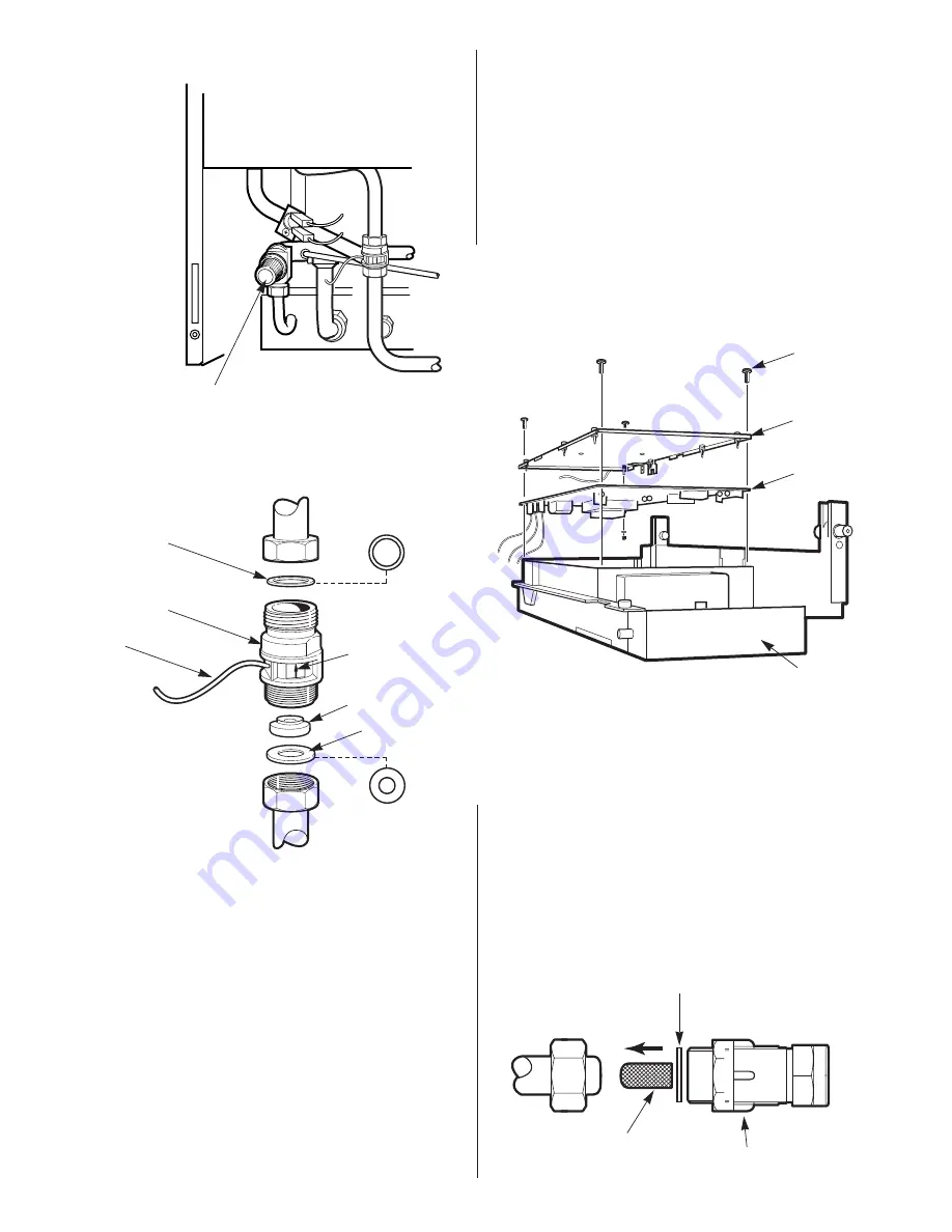
20. Control Board.
See Fig. 44.
Check that the electricity supply to the appliance is turned off.
Undo the 3 screws and remove the facia bottom panel.
Remove the two upper screws and hinge down the facia
assembly.
Carefully pull off all the connectors. Disconnect the mains supply
lead at terminal
X1
and unscrew the earth lead from the left and
side panel.
Remove the four corner screws on the rear of the facia and
separate the metal back panel from the plastic facia.
Remove the flame sense and ignitor leads from the control board.
Remove and retain the brass nut and washer.
Release the six pillars on the control board and pull the control
board forward off the back panel.
Fit the replacement board in the reverse order ensuring it is
pushed firmly onto the six pillars and clicks into place. Special
care should be taken with the brass post and nut to ensure a
good earth contact. (Check earth continuity between the
incoming earth and the appliance chassis).
Refit the facia panel and hinge the control box assembly in the
servicing position as described in Section 15.3 (c).
21. Gauze Filter.
See Fig. 45.
Remove the water flow turbine as described in section 16.4-17.
Undo the lower union nut on flow switch housing.
Undo the nut on the isolating valve and remove the mains water
inlet pipe. Carefully extract the filter from the valve end of the
pipe.
Replace the filter and refit the pipe in reverse order using a new
fibre washer.
25
Fig. 43. Water Flow turbine.
1
1 Flow turbine
2 Flow restrictor (10l Blue)
3 Fibre washer (inlet)
4 Electrical connection
5 Direction of flow
6 Fibre washer (outlet)
Fig. 42. Pressure relief valve.
Pressure relief valve.
(Turn knob anti-clockwise to test).
2
6
5
3
4
Fig. 44. Control board.
Fig. 45. Gauze Filter.
Gauze Filter
Isolating Valve
1 Facia
2 Control board
3 Rear cover
4 Fixing screws
4
3
2
1
Type
Type
Fibre Washer


