background image

38

9

8

14

3

21

1

15

13

4

22

11

7

12

10

23

20

6

25

24

2

19

18

16

24

23

20

3

5

Summary of Contents for 28i RSF

Page 1: ...entral Heating Modulated Control Modulated Control Minimum 8 5 kW Minimum 10 5 kW Maximum 27 5 kW Maximum 27 5 kW THESE INSTRUCTIONS APPLY IN THE UK ONLY AND MUST BE LEFT WITH THE USER OR AT THE GAS METER READ THE INSTRUCTIONS BEFORE STARTING WORK THEY HAVE BEEN WRITTEN TO MAKE THE INSTALLATION EASIER AND PREVENT HOLD UPS This appliance must be installed by a competent person in accordance with th...

Page 2: ...k is a vital document that must be completed by the installer at the time of installation It confirms that the boiler has been installed and commissioned according to the manufacturers instructions Without the completion of the Log book manufacturers may refuse to respond to a call out from a householder who will be advised that he or she must call back the installer who has not fulfilled his obli...

Page 3: ...ot water into cold water main can be prevented This can result in a pressure build up that may cause damage to the boiler and household devices such as showers washing machines etc In these cases we recommend that a mini expansion vessel be fitted adjacent to the boiler in the cold water pipe 2 10 Operation Domestic Hot Water With a demand for hot water the burner will light at its maximum setting...

Page 4: ...N 22mm COLD WATER INLET COMPRESSION 15mm DOMESTIC WATER FLOW COMPRESSION 15mm GAS INLET Rp 1 2 RELIEF VALVE DISCHARGE PUSH FIT 15mm CASING HEIGHT 800mm CASING WIDTH 450mm CASING DEPTH 360mm WEIGHT LIFT 42 3kg WEIGHT UNPACKED DRY 45 8kg WEIGHT PACKAGED 52kg Table 4 FLUE DETAILS HORIZONTAL FLUE mm WALL HOLE DIAMETER EXTERNAL FIX 110 INTERNAL FIX 150 STANDARD FLUE MINIMUM LENGTH 330 425 MAXIMUM LENGT...

Page 5: ...ATING bar 2 5 MINIMUM CENTRAL HEATING SYSTEM PRESSURE bar 0 5 OUTPUT TO DOMESTIC HOT WATER kw NATURAL GAS G20 8 5 27 5 OUTPUT TO CENTRAL HEATING kw NATURAL GAS G20 10 5 27 5 DOMESTIC HOT WATER SPECIFIC RATE D 30 C RISE l min 13 1 MAXIMUM DOMESTIC HOT WATER FLOW RATE 40 C RISE l min 9 8 NOx CLASSIFICATION Class 2 SEDBUK NUMBER 78 1 SEDBUK BAND D BURNER INJECTOR mm 4 5 Table 5 Refer to Section 6 DOM...

Page 6: ...thes provided that the requirements of BS 6798 and BS 5440 2 are followed Notwithstanding the instructions given in BS 5440 2 this appliance may be fitted in a compartment with no vents as long as the minimum clearances stated in Section 6 Air Supply are maintained 4 7 The airing space must be separated from the boiler space by a perforated non combustible partition Expanded metal or rigid wire me...

Page 7: ...earances at the front are for a removable panel e g a door 6 3 If the appliance is to be fitted in a cupboard or compartments with less clearance than those above minimum clearances given in Section 4 Siting The Appliance then permanent vents for cooling are required One at high level and one at low level either direct to outside air or to a room Both vents must pass to the same room or be on the ...

Page 8: ...8 7 7 Water loss must be replaced See Fig 4 The connection should be made in the central heating return as close to the appliance as possible A filling loop kit is supplied 7 8 Repeated venting loses water from the system It is essential that this water is replaced and the system pressure maintained 7 9 Connections to the mains water supply must not be made without the authority of the local Water...

Page 9: ...f the bath to prevent its immersion in bath water Alternatively the shower must be fitted with an anti syphonage device at the point of the flexible hose connections 9 12 The supply of hot and cold mains water direct to a bidet is permitted subject to local water company requirements provided that the bidet is of the over rim flushing type The outlet s should be shrouded and unable to have any tem...

Page 10: ...use with mains voltage 11 8 A facia mounted mechanical programmer is available as an optional extra Instructions are supplied with the programmer kit 11 9 A time switch or programmer can be fitted externally to the appliance 11 10 The boiler provides automatic frost protection the use of a frost thermostat is not recommended However if an external frost thermostat is considered necessary then it m...

Page 11: ...ns 15 16 X6 Pins 5 6 7 X6 Pins 14 17 18 X6 Pins 19 20 X6 Pins 3 4 Flow signal CH temp sensor DHW temp sensor CH control POT Air pressure switch MAINS PROGRAMMER CLOCK FULL SEQUENCE CONTROLLER GAS VALVE LOW VOLTAGE ELECTRONICS Microcontroller ROOM STAT X1 X2 3 2 1 1 2 3 4 6 5 RL1 X3 Pin 1 X3 Pin 2 X4 Pin 3 X5 Pin 3 X5 Pin 1 X4 Pin 1 FAN PUMP RL3 RL4 N N N N L ...

Page 12: ...lue Brown Green yellow Green yellow Programmer and room thermostat 230V X1 X2 N L Blue Fig 12 230V room thermostat connections Fig 13 230V programmer connections RN RI X2 Remove link Neutral Switched live Live RL CN Motor CI X2 Neutral Switched live Live CL Remove link ...

Page 13: ...nnect the inlet pipe and re fit Pre plumbingisnotrecommendedifnomovementinthepipesisavailable If it is necessary for the pipes to run up the back of the appliance then they must be arranged to pass behind the expansion vessel Pipework must not run horizontally within the limits of the casing It is important that the pipes are not fixed near the appliance using clips that put a strain on the connec...

Page 14: ...stance L Refer to Fig 20 and 21 The standard flue can be telescopically adjusted to any length between 425mm and 725mm Fix the flue assembly together using the self tapping screw provided Refer to Fig 18 It will only be necessary to cut the standard assembly if L is less than 425mm Cut the flue turret assembly and the terminal assembly by the same amount i e L 350 remove 75mm from each assembly Mi...

Page 15: ...et kit is available from Worcester Heat Systems NOTE A larger diameter opening in the wall is required Refer to Table 2 Prepare the flue assembly as described in Section 12 9 Fit the rubber sealing gasket centrally onto the terminal assembly and tighten the clamp Refer to Fig 23 Apply the plastic tape to the air duct in contact with the external brickwork From inside push the assembly through the ...

Page 16: ...necessary to cut the air and flue ducts of the extension to a plain length of 100mm and reduce the length of the terminal assembly i e Z 350mm remove 75mm from the terminal assembly If Z in 425 725mm it is not necessary to cut the terminal assembly or use a second extension duct as the length can be set telescopically If Z 725mm then two extension duct assemblies will be required the first assembl...

Page 17: ...7 and 28 Check there is sufficient loose lead to allow the release of the facia panel assembly and that the earth lead of the mains supply cable is longer than the live and neutral leads Fit the facia mounted clock Full instructions are sent with the programmer Refer to Fig 28 and 29 Connect any external controls ensuring that the leads pass through the appropriate clamps Refer to Fig 18 Test for ...

Page 18: ... turn Replace the cap Refer to Fig 31 Switch on the electricity supply not the gas and set the controls to give continuous operation in the CH mode When the air is expelled turn off the electrical supply and the CH control to off Check the pressure relief valve operates by turning the knob anti clockwise until it releases Lower the facia to gain acces to the relief valve Refer to Fig 32 Water shou...

Page 19: ...t state by pressing the reset button Refer to Fig 34 Turn off the hot tap The burner pressure will drop to the minimum CH setting and will ramp up to the maximum central heating pressure It should not be necessary for the gas valve to be adjusted Refer to Section 16 4 11 Switch the appliance off and then on to reset the control The burner pressure will remain at the minimum CH pressure for a perio...

Page 20: ...t water is soon discharged from the tap Close the tap and the burner will go off The appliance will then return to the central heating mode and automatically balance with the system requirements 13 12 Completion of Commissioning Disconnect the pressure gauge and tighten the test point screw Refit the cabinet If the appliance is to be passed over to the user immediately then set the controls to the...

Page 21: ...s indicated in BS 6891 15 3 DISMANTLE THE APPLIANCE To carry out a full and comprehensive service of the appliance remove the following parts to gain access to the components which need to be checked or serviced a Cabinet Front Panel Remove by lifting off the supports b Inner Casing Cover Check that the electricity supply to the appliance is turned off Remove the cabinet front panel Unscrew the fo...

Page 22: ...ter will remain in the expansion vessel pump and Gas to Water heat exchangers and extra care must be taken when removing these components b Domestic Hot Water Circuit Turn off the mains cold supply valve at the appliance and open the lowest hot water tap A quantity of water will remain in the Gas to Water heat exchanger extra care must be taken when removing this component 16 4 COMPONENT REPLACEME...

Page 23: ...king that the spark gap is 3 5 to 4 5mm 10 Flame Sensor See Fig 39 Remove the burner as described in section 15 3 h Undo the M3 screw and remove the sense electrode from the burner Fit the replacement electrode in the reverse order checking that the sense gap is 5 to 6mm 11 Gas Valve See Figs 33 and 40 Check that the electricity and gas supplies to the appliance are turned off Hinge down the contr...

Page 24: ...lectrical wires taking note of their positions Fit the replacement pump in the reverse order using new sealing washers Alternatively replace the pump head only by removing the four Allen screws on the pump remove the head and support whilst removing the electrical connections Refit the new head Open the valves and fill and re pressurise the system as described in Section 13 2 Note The direction of...

Page 25: ... retain the brass nut and washer Release the six pillars on the control board and pull the control board forward off the back panel Fit the replacement board in the reverse order ensuring it is pushed firmly onto the six pillars and clicks into place Special care should be taken with the brass post and nut to ensure a good earth contact Check earth continuity between the incoming earth and the app...

Page 26: ...ove the fan assembly as described in Section 15 3 e Unscrew the single central retaining screw and withdraw the sensor from the fan Fit the new sensor ensuring the correct orientation and carefully tighten the retaining screw Refit the fan assembly in reverse order 26 Positive Fig 46 Flue flow sensor ...

Page 27: ...ar Burner pressure automatically adjusted for range rating and then modulated to maintain set flow temperature AUTOMATIC START UP SEQUENCE CENTRAL HEATING DEMAND SATISFIED Water flow temperature monitored by central heating sensor Pump on Operating Switch or programmer and room thermostat on CENTRAL HEATING DEMAND Internal Autofrostat demand Is fan in overrun mode Air pressure switch test Fan ON S...

Page 28: ...ing sensor End of demand or central heating temperature above 70 C monitored by the central heating sensor Pump and Fan on for 4 minutes Inhibit operations for approximately 1 second 6 second delay before re ignition from any other demand Is the central heating mode interrupted AUTOMATIC START UP SEQUENCE HOT WATER DEMAND SATISFIED Pump OFF Wait for flow greater than 2 9 l min Gas valve OFF Fan re...

Page 29: ...L1 X3 Pin 1 X3 Pin 2 X4 Pin 3 X5 Pin 3 X5 Pin 1 X4 Pin 1 FAN PUMP RL3 RL4 N N N N L 18 Fault Finding Note This fault finding information is for guidance only Worcester Heat Systems cannot be held responsible for costs incurred by persons not deemed to be competent PRELIMINARY CHECKS Preliminary electrical system checks are the first electrical checks to be carried out during a fault finding proced...

Page 30: ...nsure link is fitted at X2 pins 5 6 Is mains LED flashing GO TO CHECK D GO TO CHECK K GO TO CHECK K GO TO CHECK E GO TO CHECK F GO TO CHECK O GO TO CHECK C Is control knob set for demand Is a room thermostat fitted Is room thermostat calling for heating Is programmer fitted Is programmer calling for heat Is pump running Has overheat thermostat tripped Is mains LED illuminated YES YES YES YES YES Y...

Page 31: ...e thermistor Replace harness Short circuit Faulty PCB Replace Is resistance between pins 3 4 between 690ohms 33k Is resistance between pins 19 20 between 690ohms 33k Replace fuse Is mains present at X1 pins 1 3 GO TO CHECK H GO TO CHECK I GO TO CHECK H GO TO CHECK J NO NO NO YES YES YES YES YES YES NO NO OK OK OK OK Faulty Faulty Faulty Faulty NO ...

Page 32: ...re Connector Faulty pump Is pump connector secure on the PCB X3 Is fan connector secure on the PCB X4 Is mains present at the pump connector X3 pins 1 2 Is mains present at the fan connector X4 pins 1 2 ATTACH to heat exchanger Is capillary broken Ensure appliance is cool and retest Replace overheat thermostat Is capillary firmly ATTACHED to exchanger GO TO CHECK I GO TO CHECK O GO TO CHECK L YES ...

Page 33: ...ectors Is continuity observed between each end of wire in question Faulty harness or connector Harness OK Remove appropriate connectors Faulty harness Harness OK Is short circuit observed between pair of wires in question Is resistance between terminals of thermistor between690ohms 33k Faulty thermistor YES YES YES YES NO NO YES YES NO ...

Page 34: ...re modulate Ignition OK Faulty PCB Replace Is flame sense electrode in flame Is lead secure both ends Secure lead Ensure flame sense electrode in flame at minimum burner pressure Are ignition leads connected both ends securely Does sparking occur Does ignition occur YES YES YES YES YES HARNESS OK YES YES YES YES YES NO NO NO NO NO NO NO NO NO NO GO TO CHECK G GO TO CHECK E GO TO CHECK M GO TO CHEC...

Page 35: ... It is not possible to seperately test the gas valve and the supply lead Relpace the gas valve or the lead Is live output present at X5 pins 1 2 relative to neutral at pin 3 Note Readings to be taken within 9 seconds of a demand Is gas pressure present at input to burner Gas valve OK With fan running disconnect BROWN wire DO NOT touch chassis with it Is a short circuit observed across exposed APS ...

Page 36: ...ite at a higher flow rate Faulty turbine Replace Faulty PCB Replace Disconnect the 3 way in line connector Check that there is 5V DC output from the PCB at the connector Red 5V Black 0V Faulty modulating valve Replace gas valve Remove X6 measure resistance between pins 15 16 N YES NO O Re connect the 3 way connector and open a tap to run the turbine Check that there is between 1 5 and 4 5 V DC acr...

Page 37: ... PCB Boiler Control Pactrol 423100 1 8 716 146 329 0 16 E04 582 Temperature Thermistors Elmwood 2 8 716 142 384 0 E01 900 CH Thermistor Clip 1 8 716 148 313 0 299 495 DHW Thermistor Clip 1 8 716 148 303 0 18 E01 605 DHW Flow Regulator Blue 1 8 716 141 052 0 19 324 822 Gauze Filter WHS 1 8 716 148 401 0 20 Flow Turbine SIKA VTY 1 8 716 146 160 0 21 Fan Assembly FIME 1 8 716 121 681 0 22 E01 607 Ove...

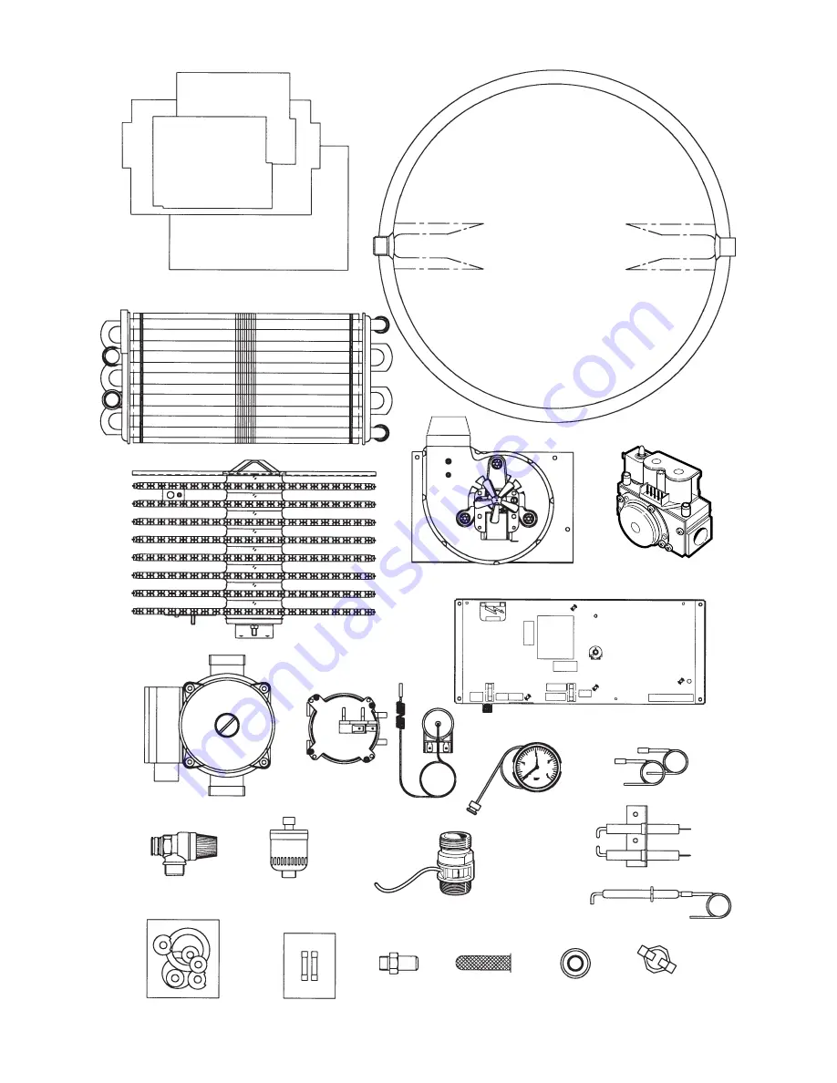
Page 38: ...38 9 8 14 3 21 1 15 13 4 22 11 7 12 10 23 20 6 25 24 2 19 18 16 24 23 20 3 5 ...

Page 39: ...39 ...

Page 40: ...old are subject to our official Conditions of Sale a copy of which may be obtained on application PUBLICATION 8 716 145 299g 02 02 Worcester Heat Systems Limited Bosch Group Cotswold Way Warndon Worcester WR4 9SW Telephone 01905 754624 Fax 01905 754619 Technical Helpline 08705 266241 www worcester bosch co uk This manual is to be used in conjunction with the variant part number of the bar code bel...

Reviews: