Manual WIP1 GB
Woodward
DOK-TD-WIP1 Rev.F
23
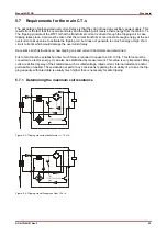
The two diagrams show the two different tripping methods. In Figure 4.3 the tripping coil is supplied directly
by the current transformer. In Figure 4.4 tripping is effected via an internal supply transformer. The result is
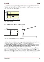
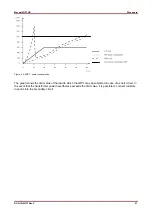
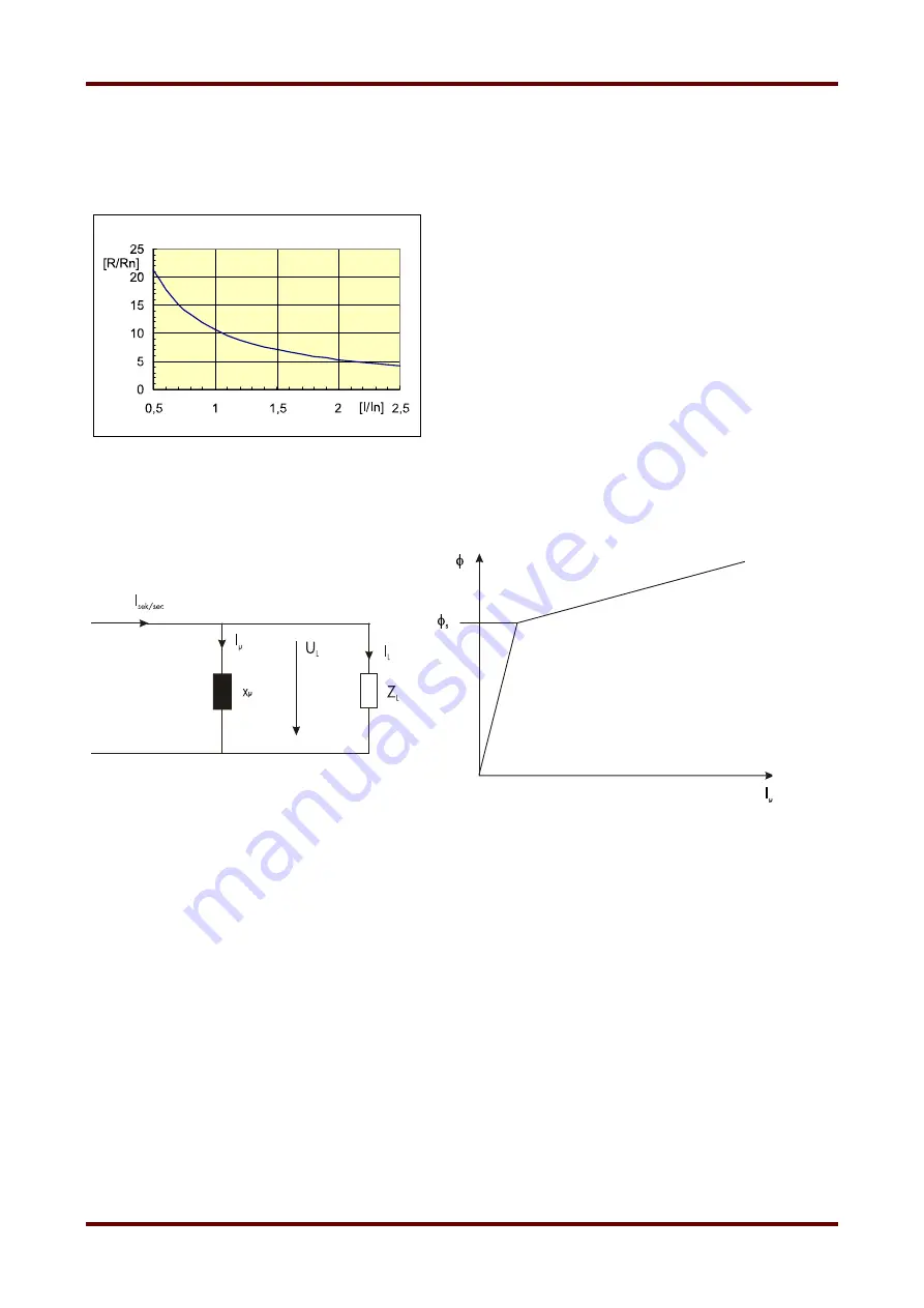
that with tripping current > 12 x In the coil resistance must not be smaller than
17 Ohm. Once it has been established that the tripping current is smaller than 12 x In, the minimum possible
coil resistance can be derived from Figure 4.5.
Figure 5.5: Minimum coil resistance
5.7.2 Characteristics of the current transformers
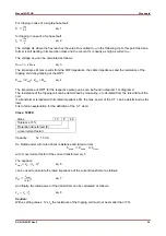
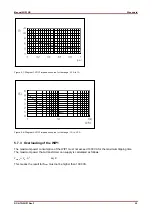
Figure 5.6: Circuit diagram of the secondary C.T. side and magnetizing curve
During normal operation the load of the current trans-former is only the WIP impedance and the impedances
of the connection cables. In case of tripping, the tripping coil also affects the transformer. Under any circum-
stances it must be prevented that this load has the effect that the transformer gets into saturation to such an
extent that the current flowing through the coil becomes too low to ensure definite tripping.
The secondary transformer current I
sec
is proportional to the primary transformer current and is a function of
the transformation ratio. This current is divided into the magnetization current of the transformer and a cur-
rent IL which flows through the current paths of the overcurrent protection system.
The flux
Ф
is proportional to the voltage U
L
and linked to the magnetization current I
µ
via the magnetization
curve. As from the value
Ф
s
the transformer moves into saturation. As a result the magnetization current
grows overproportionally and the load current decreases at the same rate. So when the transformers are di-
mensioned it must be taken into account that with a known resistance Z
L
the current I
L
is still sufficient for
tripping the coil. For this reason, the rated current of the tripping coil must be inserted for I
Sp
in the calculation
below. As the coil current I
Sp
is a direct current, it must be converted into an effective AC value by means of
eq. 1 or eq. 2. The result is, at the same time, the lowest switching point for possible tripping.


