Manual WIP1 GB
Woodward
DOK-TD-WIP1 Rev.F
18
5. Working Principle
5.1 Analog circuits
The alternating currents induced by the main current transformers provide the WIP1's supply energy and
form the measuring value. The measuring currents are galvanically isolated via the input transformers, de-
coupled from high-frequency interferences by analog RC-filters and then converted into current proportional
voltages. The noise signals caused by inductive and capacitive coupling are suppressed by an analog R-C
filter circuit. The analog voltage signals are fed to the A/D-converter of the microprocessor and transformed
to digital signals through Sample- and Hold-circuits. The analog signals are sampled at 50 Hz (60 Hz) with a
sampling frequency of 800 Hz (960 Hz), namely, a sampling rate of 1.25 ms (1.04 ms) for every measuring
quantity. (16 samples per period).
5.2 Digital circuits
The essential part of the WIP1 is a powerful microcontroller. All of the operations - from the analogue/digital
conversion to the relay trip decision - are carried out by the microcontroller digitally. The relay program is
saved in an EPROM (Electrically-Programmable-Read-Only-Memory). With this program the CPU of the
microcontroller processes the voltages applied at the analogue input circuits and calculates the basic current
harmonics. For this calculation an efficient digital filter, based on the Fourier Transformation (DFFT - Discrete
Fast Fourier Transformation) is applied to suppress high frequency harmonics and DC components caused
by fault-induced transients or other system disturbances. The relay setting values for all parameters are
saved in a parameter memory (EEPROM - Electrically Erasable Programmable Read-only Memory) and
constantly compared with the actual current by the microprocessor. If a phase current exceeds the pickup
value, an alarm is given and after the set trip delay has elapsed, the corresponding trip relay is activated. For
continuous supervision of the program flow a "hardware watchdog" is installed. In case of failure, the watch-
dog timer resets the microprocessor and gives an alarm signal via the "self-supervision" output relay. Error of
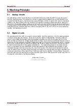
the program is indicated by the following display:
_Internal_Fault__
________________


