background image

Troubleshooting

Hydraulic Problems

Troubleshooting

HDSdoc021716

4-8

4

PROBLEM


CAUSE

SOLUTION

Hydraulic Side Supports Go 
Down Before Or At Same 
Time As Log Turner 

Dirt in sequence valve

Remove sequence valves and clean thoroughly 
with kerosene. 

NOTE:

  Be sure to reassemble 

the valve and install it in its original position on 
the cylinder

Retainer in sequence valve worn

Replace sequence valve

Low air temperature causing oil to 
thicken

Allow fluid to warm up. Synthetic fluids are 
available that allow for hydraulic operation in 
cold weather conditions (Exxon/Esso Univis 
J26).

Hydraulic Turner Goes Up 
Before Or At Same Time As 
Side Supports

Spring weakening in sequence valve

Locate sequence valve at top of turner cylinder. 
Turn heavy spring in about 1/4 turn

Dirt in sequence valve

Remove sequence valves and clean thoroughly 
with kerosene. 

NOTE:

  Be sure to reassemble 

the valve and install it in its original position on 
the cylinder

Retainer in sequence valve worn

Replace sequence valve

Low air temperature causing oil to 
thicken

Allow fluid to warm up. Synthetic fluids are 
available that allow for hydraulic operation in 
cold weather conditions (Exxon/Esso Univis 
J26).

Spring weakening in sequence valve

Locate sequence valve at bottom of turner 
cylinder. Turn heavy spring in about 1/4 turn

Summary of Contents for LT70M AH Super

Page 1: ...Table of Contents Section Page Table of Contents SW 07doc0217161...

Page 2: ......

Page 3: ...ce Manual LT70M AH Super rev A9 00 Safety is our 1 concern Read and understand all safety information and instructions before oper ating setting up or maintaining this machine August 2006 Form 1059 Th...

Page 4: ...ponents 1 23 1 19 LT40 70 S M Hydraulic Hoses 1 24 1 20 Hydraulic Blade Tensioner Assembly 1 26 SECTION 2 SETUP OPERATION 2 1 2 1 Sawmill Setup 2 1 2 2 Stationary Sawmill Setup 2 3 2 3 Portable Sawmil...

Page 5: ...y Devices Inspection 3 13 SECTION 4 TROUBLESHOOTING 4 1 4 1 Sawing Problems 4 1 4 2 Electrical Problems 4 3 4 3 Power Feed Problems 4 4 4 4 Hydraulic Problems 4 6 4 5 Engine Motor Drive Pulleys Alignm...

Page 6: ...shipping are available at additional cost If You Need Service From Europe call our European Headquarters and Manufacturing Facility in Kolo Poland at 48 63 2626000 From the continental U S call us tol...

Page 7: ...Class A Under 1300 kg B 1300 1800kg C 1800 2200 kg D 2200kg 3000kg Product No 1 LT15 2 LT20 4 LT40 Series 7 LT70 Series Length of the Trailer 20 20 Ft 24 24 35 35 Number of axles on the trailer Year...

Page 8: ...r a description of the model number When you pick up your mill you will receive a customer number Both the VIN and your customer number expedite our service to you Please write these numbers below so...

Page 9: ...fety instructions before operating this equipment Also read any additional manufacturer s manuals and observe any applicable safety instructions including dangers warnings and cautions Always be sure...

Page 10: ...ilure to do so may result in serious injury WARNING Securely fasten the feet of a stationary sawmill to the floor before operating the sawmill Failure to do so will result in serious injury or death W...

Page 11: ...when operating sawmill or loading and turning logs Failure to do so may result in serious injury DANGER Maintain a clean and clear path for all necessary movement around the mill and lumber stacking a...

Page 12: ...e below bed level before loading a log onto the bed Failure to do so may result in machine damage or cause misalignment CAUTION Before loading a log be sure the cutting head is moved far enough forwar...

Page 13: ...UTION Never use grease on the mast rails as it will collect sawdust CAUTION Do not use chain lube It causes sawdust buildup in chain links CAUTION Do not over tension the up down chain Over tensioning...

Page 14: ...s who have read and understood the entire operator s man ual should operate the sawmill The sawmill is not intended for use by or around children IMPORTANT It is always the owner s responsibility to c...

Page 15: ...ntain a clean and clear path for all necessary movement around the sawmill and lumber stacking areas Failure to do so will result in serious injury Dispose Of Sawing By Products Properly IMPORTANT Alw...

Page 16: ...t with hot motor components can cause serious burns Therefore never touch or perform service functions on a hot motor Allow the motor to cool sufficiently before beginning any service function DANGER...

Page 17: ...while working around an open electrical circuit WARNING Remove the blade before performing any service to the motor or sawmill Failure to do so may result in serious injury DANGER Never clean the blad...

Page 18: ...decals are clean and readable Replace all damaged safety decals to prevent personal injury or damage to the equipment Contact your local distributor or call your Customer Service Representative to or...

Page 19: ...rt Motor Drive Belt E25 3B HB 2462La 089464 Up Down Drive Belt AC mills HA 670 091328 Blade Pulley Belts B72 5 1 1 To insure proper blade tracking use Goodyear Dayco Super II or Browning belts only 01...

Page 20: ...Information 099221 CAUTION Keep all persons a safe distance away from work area when operating the machine 098176 CAUTION Keep away from debarker blade 096316 CAUTION Do not open or close the electri...

Page 21: ...l Information HDSdoc021716 1 13 1 096317 CAUTION Disconnect power supply before opening the box 085977B No lift the machine grasping by the element 086099 CAUTION Keep away hot parts 099222 CAUTION Sa...

Page 22: ...rmation 099542 CAUTION Trailer 096321 Blade movement direction 505189 Lever of tensioner s ball valve S12004G CAUTION Always wear safety goggles when operating the sawmill S12005G CAUTION Always wear...

Page 23: ...rmation HDSdoc021716 1 15 1 501465 CAUTION Always wear safety boots when operating the sawmill 501467 Lubrication Point P11789 70 Aligning the blade on the wheels P85070 CE safety certification 099401...

Page 24: ...city See Table 1 4 The LT70 Super sawmills can accept logs as listed below S20097 2930 RPM Motor rotation direction Softwood Medium Hardwood Frozen Timber or Dense Hardwood 15 18 5kW 20 25HP Electric...

Page 25: ...r BX24 2000kg Failure to do so may result in machine damage or serious injuries Engine Motor Type 1 1 Use diesel fuel for D42 Manufacturer Model Number Power Other Specifications Electric Motor 25KM 2...

Page 26: ...l measurement was taken in accordance with PN EN ISO 3746 Standard The noise exposure level given above concerns an 8 hour work day Value for associated uncertainty K 4dB 2 The measured values refer t...

Page 27: ...ow LT70M Super 26 2 8 m 6 6 2 m 8 2 2 5 m 7 8 2 4 m 3491 lbs 1571 kg 3916 lbs 1762 kg 1 Length from hitch to chain bracket 2 Width from fender to fender 3 Height from ground to mast Placing head in ma...

Page 28: ...oot mean square value of weighted acceleration to which the whole operator s body is subjected does not exceed 0 5 m s2 1 16 Components Airflow 1200 m3 h 3937ft3 h Inlet diameter 100 mm 5 9 Motor powe...

Page 29: ...Components Safety General Information HDSdoc021716 1 21 1 See Figure 1 1 The major components of the Wood Mizer LT70 are shown below FIG 1 1 Motor Mount Control Panel Box Optional trailer axle Hydrau...

Page 30: ...HYDRAULIC SCHEMATIC 25 PSI Manifold H1 H2 V1 Clamp In Out Turner Up Down Side Support C4 V2 Clamp Up Dn Front Toeboard C5 Loading Arms Optional C6 V3 V3 C4 H8 H10 H11 H12 H13 H14 H25 H26 H27 H28 Rear...

Page 31: ...ic P12846 Hyd Cylinder 2 1 2 Bore x 8 Stroke C4 P12845 J D Hydraulic P12845 Hyd Cylinder 2 Bore X 6 Stroke C5 C6 014482 J D Hydraulic 014482 Hyd Cylinder 1 1 2 Bore x 6 Stroke C7 C8 P12847 J D Hydraul...

Page 32: ...151 1 4 Front Toe Board Base LT40M 087776 H7 Pink 4 2m 166 3 8 Side Support Cylinder Base LT40S 087791 4 77m 188 3 8 Side Support Cylinder Base LT40M 087777 H8 Plain 4 2m 166 3 8 Side Support Cylinde...

Page 33: ...H15 Blue 4 34m 171 3 8 Loading Arm Cylinder Top LT40S 087795 4 9m 193 3 8 Loading Arm Cylinder Top LT40M 087781 H16 Red 4 34m 171 3 8 Loading Arm Cylinder Bottom LT40S 087795 4 9m 193 3 8 Loading Arm...

Page 34: ...neral Information Hydraulic Blade Tensioner Assembly 1 1 26 HDSdoc021716 Safety General Information 1 20 Hydraulic Blade Tensioner Assembly FIG 1 3 HYDRAULIC SCHEMATIC 600301 12 VDC 8 1 7 9 6 5 3 4 2...

Page 35: ...he sawmill can be operated with the sawdust collection system only The sawmill can t be operated outdoor when it is raining snowing and in case of rain snow the sawmill must be stored under roof or in...

Page 36: ...n guard If the rotation direction is incorrect invert the phases in the phase inverter in the power socket electric box Setting the phases in the phase inverter correctly will ensure correct rotation...

Page 37: ...ontrol box lock bracket Remove the control box lock bracket from the saw head track rails 2 Unhook the carriage safety chain located at the bottom of the vertical mast 3 Turn the key switch on the con...

Page 38: ...ame tube The hydraulic control levers will only work when the cutting head is close enough to the front end of the mill to touch the power strip 5 Raise the side supports that will prevent a log from...

Page 39: ...1716 2 5 2 2 2 1 Sawmills with cable guide optional equippment See Figure 2 2 The figure below shows operator s position of the LT70MAH Super with cable guide See Figure 2 2 The figure below shows set...

Page 40: ...Setup Operation Sawmills with cable guide optional equippment 2 2 6 HDSdoc021716 Setup Operation FIG 2 2 LT70MSUPER RC...

Page 41: ...ent Setup Operation HDSdoc021716 2 7 2 See Figure 2 3 The electrical wires should be installed on the cable guide as shown below See Figure 2 4 The figure below shows how the electrical wires should b...

Page 42: ...onal equippment 2 2 8 HDSdoc021716 Setup Operation CAUTION Be sure the larger diameter cables are mounted to the upper brackets of the roller hangers and the smaller diameter cables are mounted to the...

Page 43: ...l frame when operating a sawmill with adjustable outriggers Failure to do so will result in serious injury or death The adjustable outriggers are intended to support the saw frame with assistance from...

Page 44: ...ble the battery operated accessories Use the up down switch on the control panel to raise the cutting head from the carriage rest pin Remove the locking pin and swing the rest pin down below bed lRemo...

Page 45: ...log from falling off the side of the mill when loaded See Figure 2 4 2 4 Middle track cover Before operating the sawmill do as follows 1 Clean the upper and lower rails to remove any sawdust and rust...

Page 46: ...up Operation See Figure 2 5 CAUTION Install the track cover so that it lightly touches the track rail If the wiper presses too firmly against the rail it can cause the power feed to bind FIG 2 5 60030...

Page 47: ...ee Section 2 6 until the wheel is pulled in and the blade is lying loose in the blade housing Lift the blade out of the blade housing When installing a blade make sure the teeth are pointing the corre...

Page 48: ...tem See Figure 2 6 To tension the blade use the tension handle when the ball valve handle is in 1 working position To release shift the ball valve handle in 0 loosing position The blade tension handle...

Page 49: ...s will cause tension to change Adjust the tension handle as necessary to maintain the recommended tension level CAUTION Release the blade tension when the mill is not in use for example at the end of...

Page 50: ...sitions itself on the blade wheels 3 Check if the blade is properly positioned on the blade wheels See Figure 2 7 Position 1 1 4 wide blades so the gullet is 3 0 mm out from the edge of the blade whee...

Page 51: ...to track the blade properly See Section 5 3 for complete blade wheel alignment instructions 5 Adjust the blade tension if necessary to compensate for any changes that may have occurred while adjusting...

Page 52: ...blade is disengaged and all persons are away from the blade before starting the engine Failure to do so may result in serious injury WARNING Always wear eye ear respiration and foot protection when o...

Page 53: ...ouch the power strip See Figure 2 9 Sawmills equipped with A DHS7 hydraulic system have fourteen control levers to load clamp turn and level logs Use the hydraulic control levers to get the mill ready...

Page 54: ...der so the legs rest on the ground CAUTION Be careful when manually lowering the log loader Do not drop the loader onto the ground 6 Lower the loader lever to lower the loading arm as far as it will g...

Page 55: ...centered with the sawmill bed The log turner will operate much easier if the log is centered on the sawmill bed 3 Raise the side supports 4 Raise the loader lever to raise the log onto the sawmill bed...

Page 56: ...mp by raising the clamp in out lever Clamp the log against the side supports 5 Lower the side supports 6 Lower the turner lever to lower the turner arm below the log To Turn Logs Optional Procedure If...

Page 57: ...ith logs shorter than 3 5m can be used They allow to find optimal position of the log on the bed and prevent distortions during cutting 1 Raise the front rear clamp up down lever to raise the clamp 2...

Page 58: ...ntrol panel Push the switch up to raise the cutting head push the switch down to lower the cutting head Hold the switch in position until the cutting head reaches the desired height then release The u...

Page 59: ...usted to clear the widest section of the log by less than 1 25 4 mm 2 Use the blade guide toggle switch on the control panel to adjust the outer blade guide as necessary Push the switch to the left to...

Page 60: ...r feed operation The carriage forward reverse switch controls the direction in which the carriage travels Turn the forward reverse switch upward to move the carriage forward Turn the switch down to mo...

Page 61: ...moving Disengage the clutch brake lever up or the optional blade switch down to stop the blade and drop the engine to idle Remove the board that you have just cut from the log Always disengage the bl...

Page 62: ...nto the log slowly See Section 2 13 Once the blade completely enters the log increase the feed rate as desired Always try to cut at the fastest speed you can while keeping an accurate cut Cutting too...

Page 63: ...he log is square Cut boards from the remaining cant by adjusting the blade height for the thickness of boards that you want Example Remember that the blade cuts a 1 16 1 8 1 6 3 2 mm wide kerf If you...

Page 64: ...ide supports halfway up the flitch height Wider flitches should be placed to the clamp side When they are edged flip them over to edge the second side without disturbing the other flitches or without...

Page 65: ...ath of the blade Failure to do so will result in serious injury or death CAUTION If you choose to leave the blade engaged raise the blade to clear the log before returning the carriage Failure to do s...

Page 66: ...ard Quarter Scale and Grade Hardwood Quarter Scale Both scales are provided with four sets of marks Each set represents a specific lumber thickness Saw kerf and shrinkage allowance are included but ac...

Page 67: ...ow when the power feed is activated in the forward direction The solenoid will stop the water flow when the feed switch is returned to the neutral position Not all types of wood require the use of the...

Page 68: ...witch to off 0 NOTE If your sawmill is equipped with LubeMizer System please refer to LubeMizer Operation Manual 2 20 Preparing The Sawmill For Transportation The Wood Mizer trailer package for the LT...

Page 69: ...e Sawmill For Transportation Setup Operation HDSdoc021716 2 35 2 See Figure 2 15 5 Lower the saw head until it is it contacts the stop blocks on the mast rails Secure the saw head with locking clamp F...

Page 70: ...stop bolts can cause saw head damage especially during mill transportation 6 If necessary adjust the two stops located at the bottom of the mast so the saw head contacts them after it is lowered 3 4 1...

Page 71: ...ions lists only part of the maintenance procedures that need to be performed in LT70 sawmills Be sure to refer to option and engine manuals for other maintenance procedures 3 1 Wear Life See Table 3 1...

Page 72: ...ock should be replaced If you have access to the appropriate equipment you can grind or mill the blocks to a new flat surface and reuse them It is recommended you develop a routine schedule for replac...

Page 73: ...ming in the blade These cracks will lead to premature blade breakage If the blade breaks during operation and the blade has multiple stress cracks the blade could shatter into several pieces and escap...

Page 74: ...he blade screw in the top center of the C frame is 1 16 1 5 mm away from the blade If not loosen the nut and adjust the screw as necessary Check the screw every blade change Failing to maintain this a...

Page 75: ...articles from the rails CAUTION Keep track rails free of rust Formation of rust on the track rail in the areas where the cam bearings roll can cause rapid deterioration of the track rail s surface Lub...

Page 76: ...ION Reinstall the track wiper so that it lightly touches the track rail If the wiper presses too firmly against the rail it can cause the power feed to bind FIG 3 3 Clean sawdust from track roller hou...

Page 77: ...vomiting contact a physician KEEP OUT OF THE REACH OF CHILDREN 3 7 Miscellaneous Maintenance 1 Oil all chains with Dexron III ATF every fifty hours of operation CAUTION Do not use chain lube It causes...

Page 78: ...serious injury Periodically check the drive belt for wear Replace any damaged or worn belts as needed See Figure 3 4 Adjust proper drive belt tension using the bolt located between the drive side whe...

Page 79: ...t nut to adjust the bolt until the center of the chain can be deflected 3 4 1 9cm with a 5 lb 2 3 KG deflection force CAUTION Do not over tension the chain Over tensioning the chain may lead to early...

Page 80: ...10 HDSdoc021716 MAINTENANCE Periodically check the belt for wear Replace any damaged or worn belts as needed 2 When oil leaks from the gear reducer please contact Customer Service FIG 3 4 Mounting Bo...

Page 81: ...outside in humid weather drain and replace two quarts 95 liters of fluid every six months This will drain any accumulated water and help prevent pump failure due to water ingestion It also will preven...

Page 82: ...hes if they worn to a length of 1 4 or shorter Do not operate the hydraulic system if the pump motor brushes are worn shorter than 1 4 Damage to the pump motor may result 2 Periodically check all hydr...

Page 83: ...n of the control circuits with the E STOP button pressed Blade cover safety switch 1 and its circuit inspection Blade cover safety switch 2 and its circuit inspection Motor brake and its circuit inspe...

Page 84: ...essed try to start the debarker blade motor and move the debarker arm in and out The debarker should not work With E STOP button pressed try to move the blade guide arm in and out The blade guide arm...

Page 85: ...ade motor should remain stopped Close the blade housing cover 2 The blade motor should remain stopped until it is restarted with the START button 5 Motor brake and its circuit inspection Turn on the b...

Page 86: ...pener Manual Blades Break Prematurely Rubber belts on blade wheels worn to a point that blade contacts metal pulley look for shiny spots on edge of wheels Change blade wheel belts B 57 Poor sharpening...

Page 87: ...operly adjusted Adjust up down chain Drive belt s loose Adjust drive belt s Lumber Is Not Square Vertical side supports not square to bed Adjust side supports Blade not parallel to bed rails Adjust be...

Page 88: ...power feed which causes thermal overload Remove sawdust from pulleys and operate normally Reset overload and operate normally Up Down Or Power Feed Switches Remain Engaged When Switch Is Released Worn...

Page 89: ...od condition and positively close circuit Components are loose or wires are broken Replace or repair PC board Power Feed Is Jerky When Shaft Of Feed Rate Dial Is Moved Back And Forth Variable speed sw...

Page 90: ...ain is centered on cam follower bearing Clean and lubricate chain Adjust chain tension Allow motor to cool before restarting Chain is improperly tensioned Adjust chain tension Allow motor to cool befo...

Page 91: ...ower rail Check contact and rail for tarnish or loose wires Clean as neccesary Circuit breaker tripped Reset breaker Defective pump motor Replace Poor cable connection Check cable connection Defective...

Page 92: ...draulic operation in cold weather conditions Exxon Esso Univis J26 Pump Motor Runs Continuously When Power Contact Is Made Solenoid is stuck closed Tapping the solenoid may solve this problem temporar...

Page 93: ...tions Exxon Esso Univis J26 Hydraulic Turner Goes Up Before Or At Same Time As Side Supports Spring weakening in sequence valve Locate sequence valve at top of turner cylinder Turn heavy spring in abo...

Page 94: ...e Turn the dial and move the shaft back and forth again Repeat several times If the jerkiness occurs at the same location on the dial several times you need to replace the variable speed switch 4 7 Po...

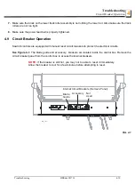
Page 95: ...ill controls are equipped with manual reset circuit breakers to protect the electrical circuits See Figure 4 1 The blade guide and accessory breakers are located inside the control box Remove the circ...

Page 96: ...nsport the sawmill over rough terrain 5 1 Routine Alignment Procedure Blade Installation 1 Remove the blade and check the blade wheels Remove any sawdust buildup from the surface of the wheels 2 Insta...

Page 97: ...1 Move the saw carriage so the blade is positioned over a bed rail Adjust the blade guide arm to 1 2 15 mm from full open 2 Raise the saw head so the bottom of the blade measures 14 3 4 375 mm from t...

Page 98: ...t bolts To lower the outside of the saw head loosen the adjustment bolts and tighten the stop bolts Recheck the measurement from the blade to the bed rails and adjust the stop bolts and adjustment bol...

Page 99: ...de properly causing inaccurate cuts A loose blade guide arm can also cause blade vibration 1 Adjustthe blade guide arm in to 1 2 15 mm from fully closed 2 Manually try to move the arm up and down If y...

Page 100: ...and the back of the blade If the sawmill is equipped with optional all ceramic guides measure from the back of the blade to the back roller See Figure 5 4 4 Adjust the blade guide arm to 1 2 15 mm fro...

Page 101: ...sen the left bolt and tighten the right bolt Retighten the jam nuts and recheck the blade guide arm horizontal tilt 5 Now check the vertical tilt of the blade guide arm Move the saw carriage so the bl...

Page 102: ...he blade guide mounting block to the bed rail This measurement should be 15 375 mm or slightly higher because the saw head is tilted up 1 26 1 mm on the outside See Saw Head Tilt If the blade guide is...

Page 103: ...justment bolt jam nuts To tilt the blade guide arm down loosen the right bolt and tighten the left bolt To tilt the blade guide arm up loosen the left bolt and tighten the right bolt Retighten the jam...

Page 104: ...ooth or burr and is lying flat against the bottom of the blade See Figure 5 8 3 Move the carriage so that the front end of the tool is positioned above the bed rail Measure the distance from the bed r...

Page 105: ...the blade guides are tilted in the wrong direction horizontally the back of the blade may contact the flange as the roller is spinning down causing it to push the blade away from the guide roller 1 Re...

Page 106: ...dge of the blade and the other end of the tool A he roller should be tilted slightly to the left A 1 8 3 mm less than B 1 8 3 mm See Figure 5 11 Loosen the jam nuts on the horizontal tilt adjustment s...

Page 107: ...k the tilt of the blade 5 Repeat the above steps for the inner blade guide roller assembly NOTE Once the blade guides have been adjusted any cutting variances are most likely caused by the blade See t...

Page 108: ...ened 1 Measure the distance between the flange on the inner blade guide roller to the back edge of the blade This distance should measure 1 16 1 5 mm Adjust the roller back or forward if necessary See...

Page 109: ...g the side support down 3 Pull back at the top of the support to eliminate slack as if a log were being clamped against it See Figure 5 13 4 Check the angle of each support with a square on the board...

Page 110: ...the inner blade guide assembly 2 View the blade height scale with eyes level with the indicator The scale should indicate the actual distance from the blade to the bed rail Adjust the indicator if nec...

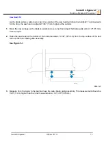
Page 111: ...Installation 1 Remove the blade and replace the balde wheel belts New blade wheel belts are required to perform the complete alignment procedure 2 Blow sawdust off of the blade guide assemblies Remov...

Page 112: ...age so the front end of the tool is positioned over the first bed rail Measure from the bottom of the tool to the top surface of the bed rail 3 Move the saw carriage so the rear of the tool is positio...

Page 113: ...ame distance from the bed rail within 1 16 1 5 mm 6 Remove the tool from the blade and reattach it near the outer blade guide assembly 7 Measure from the tool to the bed rail at both ends of the tool...

Page 114: ...am nuts To tilt the wheel down loosen the top adjustment screw one quarter turn Loosen the jam nut on the bottom adjustment screw and tighten the screw Tighten the top and bottom jam nuts 8 Recheck th...

Page 115: ...See Figure 5 19 Use the cant control adjustment to adjust the idle side blade wheel If the blade is too far forward on the wheel turn the cant control clockwise If it is too far back on the wheel turn...

Page 116: ...e wheel To move the blade back on the wheel loosen the jam nut on the adjustment screw and tighten the screw Tighten the jam nut To move the blade out on the wheel loosen the jam nut on the adjustment...

Page 117: ...f the pivot bed rail support All measurements should be equal See Figure 5 21 To adjust the saw head tilt use the bolts located at the bottom of the saw head mast Loosen the three sets of four retaini...

Page 118: ...op Adjust the clamp down to its lowest postion Move the saw head forward until it is positioned over the clamp Raise the saw head until the blade measures 15 5 16 385 mm from the clamp at its lowest p...

Page 119: ...pivot rail 10 Move the saw head so the blade is positioned over the center of the front main bed rail 11 Measure the distance between the bottom of the blade and the bed rail at each end of the bed ra...

Page 120: ...g screws and apply a lubricating oil such as 10W30 or Dexron III to each screw This will prevent the screws and threaded holes from corroding and make screw adjustments easier 1 Inspect the guide disk...

Page 121: ...aise the blade guide assembly so it does not touch the blade NOTE Before adjusting the top bolt unload pressure on the bolt by turning 1 2 turn in the opposite direction it was last adjusted With the...

Page 122: ...guide arm in to 1 2 15 mm from fully closed 2 Manually try to move the arm up and down If you can move the arm by hand you will need to tighten the arm rollers See Figure 5 24 Loosen the jam nuts and...

Page 123: ...guide arm to 1 2 15 mm from fully open and remeasure the distance from the roller flange to the back of the blade The two measurements should be the same If not adjust the outer rollers in or out to...

Page 124: ...the left bolt and tighten the right bolt Retighten the jam nuts and recheck the blade guide arm horizontal tilt 5 Now check the vertical tilt of the blade guide arm Move the saw carriage so the blade...

Page 125: ...rm to 1 2 15 mm from fully open Measure the distance from the bottom of the blade guide mounting block to the bed rail This measurementshould be 15 376 mm If the measurements are not the same adjust t...

Page 126: ...justment bolt jam nuts To tilt the blade guide arm down loosen the rear bolt and tighten the front bolt To tilt the blade guide arm up loosen the front bolt and tighten the rear bolt Retighten the jam...

Page 127: ...ith a tape from the top of the rail to the bottom of the blade See Figure 5 29 Turn the top adjustment bolt counterclockwise to lower the assembly until the blade guide roller deflects the blade down...

Page 128: ...e alignment tool on the blade Position the tool close to the outer blade guide roller Be sure the tool does not rest on a tooth or burr and is lying flat on the blade See Figure 5 30 3 Move the carria...

Page 129: ...screw Tighten the jam nuts and recheck the tilt of the blade 6 Move the blade guide alignment tool close to the inner blade guide roller assembly and repeat the above steps Adjust the vertical tilt o...

Page 130: ...lignment tool from the blade and adjust the blade guide arm halfway in 2 Remove the clip from the blade guide alignment tool Place the tool against the face of the outer blade guide roller See Figure...

Page 131: ...screw To tilt the roller right loosen the left screw and tighten the right screw Tighten the jam nuts and recheck the tilt of the blade 5 Repeat the above steps for the inner blade guide roller assemb...

Page 132: ...4 Loosen the top and one side screw shown and rear adjusting bolt if necessary Tap the blade guide forward or backward until properly positioned Retighten the screws and jam nuts 2 Measure the distanc...

Page 133: ...s but leave snug Determine which outer bolt to use to tilt the blade guide assembly as desired Loosen the jam nut and turn the bolt until the alignment bar is parallel to the blade Retighten the jam n...

Page 134: ...ustment tool to raise the bottom disk to 0 3 0 5 mm from the blade Use the provided shim to set the distance from the disk to the blade Tighten the bottom disk mounting bolt and clamp bolt 3 Turn the...

Page 135: ...t is vertical 3 Pull back at the top of the support to eliminate slack as if a log were being clamped against it See Figure 5 37 4 Check the angle of each support with a square on the board 5 The side...

Page 136: ...Sawmill Alignment Clamp Stop Stop Bolt Adjustment 1 Once the side supports are aligned pivot them down to their horizontal position 2 Tie a string across the face of the side supports Loosen the clam...

Page 137: ...ted 1 16 1 5 mm higher at the outside 1 Move the saw carriage so the blade is positioned over a bed rail Adjust the blade guide arm to 1 2 15 mm from full open The saw head should still be adjusted so...

Page 138: ...tighten the adjustment bolts To lower the outside of the saw head loosen the adjustment bolts and tighten the stop bolts Recheck the measurement from the blade to the bed rails and adjust the stop bol...

Page 139: ...th of the blade to the top of the bed rail near the inner blade guide or stainless steel sleeve if applicable See Figure 5 40 2 View the blade height scale with eyes level with the indicator 3 Loosen...

Page 140: ...lining occur in an application at the same time the influencing factors must be added for calculating the wear Inspections To ensure safe and trouble free operation spring applied brakes must be check...

Page 141: ...an increased initial rate of wear Checking the rotor thickness DANGER The motor must not be running when checking the rotor thickness Remove the motor cover and seal ring if mounted Measure the rotor...

Page 142: ...0 Model No of manufacturer Applicable EC Directives EC Machinery Directive 2006 42 EC EC Electromagnetic Compatibility Directive 2004 108 EC Applicable Harmonized Standards PN EN ISO 12100 2012 PN EN...

Reviews: