


-13-
- 8” Jointer is equipped with the switch with emergency
stop cover, waterproof and dustproof, and wrong touch
switch lock, which can prevent accidents.
- The start button is located under the emergency stop
cover. After opening the emergency stop cover, press the
green “I” to start the machine.
- To turn off the machine, directly hit the emergency stop
cover with force, and the equipment can be stopped.
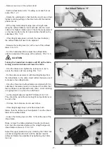
Feed the wood into the jointer
with the grain to obtain a smooth surface. FIG 6.2.
Avoid feeding work into the jointer against the grain. The
result will
be chipped and splintered edges
on the wood surface.
6.1 STARTING AND STOPPING JOINTER
6.2 DIRECTION OF GRAIN
WARNING
WARNING
WARNING
This operations section was designed to give instructions on the basic operations of this jointer. How-ever, it
is in no way comprehensive of every jointer operation. It is strongly recommended that you read books, trade
magazines, or get formal training to maximize the potential of your jointer while minimizing the risks.
WARNING
6. OPERATION
5.9 SWITCH POST INSTALLATION
The switch is prewired to the motor. No additional
wiring is needed at this point.
- Locate the Switch Post and position it to the rear on the
infeed table.
The two M8 x 20mm Allen bolts and two 8mm flat
washers are pre-installed in the rear of Infeed Table
casting.
Before turning on the machine, review the safety
precautions listed . Make sure that you fully
understand the features, adjustments and capabilities
of the machine that are outlined throughout this
manual.
This jointer is designed to surface natural wood ONLY
.
CAUTION
CAUTION
FIG.5.9
FIG.6.1
FIG.6.2
- Install the Switch Post to the rear of the infeed table and secure using two M8 x 20mm Allen bolts and two 8mm flat
washers. A-FIG.5.9.
DO NOT continuously use the jointer at the maximum depth of cut, 1/8 in. (3mm), as it will put exces-sive stress
on the motor which will damage it.


