


-10-
FIG.5.2.1
FIG.5.2.2
FIG.5.3.1
FIG.5.3.2
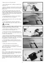
- Loosen the four 13mm motor mounting bolts and nuts on
the outer slide rail.
- Thread the drive belts through the opening in the stand
and hang it on the spindle pulley.
- Lift up the motor and center the drive belts on the motor
pulley. Fig. 5.2.1
- Allow the weight of the motor to determine the proper
belt tension. The drive belts should be set between 3/8”
and 1/2” deflection when side pressure is applied.
Fig. 5.2.2.
- Tighten the four 13mm motor mounting bolts and nuts on
the outer slide rail.
The procedure below will ensure drive belt longevity
and reduce vibration. If the pulleys are not set cor-
rectly, excess wear to the belts and power transfer
may be reduced.
5.2 DRIVE BELT INSTALLATION
5.3 DRIVE BELT & PULLEY ALIGNMENT
WARNING
- Loosen the four 13mm motor mounting nuts holding the
motor onto the inner slide rail. Fig. 5.3.1.
- Using a straight edge (Fig.5.3.2.) align the face of the
cutterhead pulley to the motor pulley by sliding the motor
in the appropriate direction.
- After the pulleys are properly aligned, tighten the four
13mm motor mounting nuts holding the motor onto the
inner slide rail. Fig. 5.3.1
- Install the rear door of the jointer stand which was
removed in section “Jointer Top Assembly”, 5.1.


