background image

To avoid electrocution or fire, any maintenance or repair to electrical system should be done only 

by qualified electricians using genuine replacement parts.

WARNING

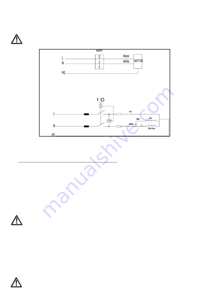
3.3  ELECTRICAL CONNECTION

- Electrical installation should be carried out by competent, qualified personnel.

- The mains connection should be made using the terminal box.

- Replacement of the power supply cable should only be done by a qualified electrician. 

-7-

3.4  NOISE LEVEL

                                                     No load                Load

            Sound Pressure Level        < 80dB(A)          < 90dB(A)
            Sound Power Level            < 90dB(A)          < 100dB(A)

The noise levels measured are emission levels and not necessarily the safe working level. Although there is a 

correlation between the emission levels and the exposure levels, this cannot be used reliably to determine whether or 

not further precautions are required. The factors which affect the actual level of operator exposure include the duration 

of exposure, the ambient characteristics and other sources of emission, for example, the number of machines and 

other adjacent machining. The permitted exposure values may also vary from country to country. Nevertheless, this 

information allows the user of the machine to better evaluate the dangers and risks.

Other factors which reduce exposure to noise are:

- correct tool choice

- tool and machine maintenance

- use of hearing protection systems (e.g. headsets, earplugs,...)


WARNING

Please use the hearing protection systems if the above mentioned noise levels exceed 95dB(A).

3.5  DUST EXTRACTION

If this band saw is operated indoors it is recommended to have it connected to a dust collector. The suction connector, 

supplied with the machine, has to be fitted to the dust ejection port of the saw for this purpose. The diameter of the 

suction connector is 100mm (4”).

- Workmen working in operations processing oak or beech timber where found to develop more often cancer of the 

mucous membrane of the nose (adenocarciome of the inner nose) then other workers.

- Experience shows that skin contact with oak or beech dust does not cause cancer

Wood dust and chips, together with an ignition source and the oxygen in the ambient air, can 

cause fires and explosions, injuries and allergies.

WARNING

Summary of Contents for HB350A

Page 1: ...THIS MANUAL FOR FUTURE REFERENCE 4 3 49 5 3 LWAYS FOLLOW THE INSTRUCTIONS PROVIDED WITH THE MANUAL LWAYS WEAR SAFETY GLASSES WHEN USING WOODWORKING EQUIPMENT LWAYS DISCONNECT THE POWER BEFORE ADJUSTING ANY EQUIPMENT AILURE TO OBSERVE PROPER SAFETY PROCEDURES AND GUIDELINES CAN RESULT IN SERIOUS INJURY 7 2 O NOT ALLOW FAMILIARITY GAINED FROM FREQUENT USE OF YOUR MACHINE AND ACCESSORIES TO BECOME CO...

Page 2: ...AND INFORMATION SIGNALS 3 SPECIFICATIONS 3 1 MAIN COMPONENTS 3 2 TECHNICAL SPECIFICATION 3 3 ELECTRICAL CONNECTION 3 4 NOISE LEVEL 3 5 DUST EXTRACTION 4 INSTALLATION AND OPERATION 4 1 INSTALLATION ZONE CHARACTERISTICS 4 2 INSTALL OF LOOSE PARTS INTRODUCTION 5 MAINTENANCE 5 1 CHANGING AND SETTING THE BLADE 5 2 BLADE GUIDING 5 3 FIX FLANGE 6 TROUBLE SHOOTING 7 DIAGRAMS AND COMPONENTS ...

Page 3: ...d staff shall use and service the machine after reading this manual Respect the accident prevention regulations and the general safety and industrial medicine rules Indicates imminent risks which may cause serious injury to the operator or other persons Be careful and scrupulously follow the instructions A statement advising of the need to take care lest serious consequences result in harm to mate...

Page 4: ...ine or the system is operating Before start machine check if the blade is properly assembled After starting machine check if turning direction of bladeis right start to work after revolving speed is stable Many unpleasant experiences have shown that anybody may wear objects which could cause serious accidents Therefore before starting working take any bracelet watch or ring off Button the working ...

Page 5: ...the machine is powered Carefully read and understand the manual before using the machine INFORMATION SIGNALS Indicate the technical characteristics direction of rotation and inclination block and release etc Carefully following the directions to simply the use and adjustment of the machine The signals are graphically described and do not require further explanation WARNING Accident caused by unqua...

Page 6: ... 9 Guide Rail 10 Hand wheel 11 Lock handle 12 Blade guard 13 Upper wheel 14 Lower wheel 6 SPECIFICATION HB350 Motor voltage 230V 50Hz Power 2200W Blade length 3114mm Blade width 19 26mm Max Blade Height Movement Distance 300mm Max Cutting Width Log Diameter 400mm Blade speed 1040m min Max cutting length 1500mm Throat Depth 340mm 1 2 3 4 5 6 7 8 9 10 11 12 13 14 ...

Page 7: ...hines and other adjacent machining The permitted exposure values may also vary from country to country Nevertheless this information allows the user of the machine to better evaluate the dangers and risks Other factors which reduce exposure to noise are correct tool choice tool and machine maintenance use of hearing protection systems e g headsets earplugs WARNING Please use the hearing protection...

Page 8: ...system connection shall be closeto the selected machine setting and it must be conveniently lighted 4 INSTALLATION AND OPERATION 4 2 1 INSTALL STAND Tools required for assembly Socket wrench Exagon socket wrench Put the long beam B onto short beam A align themounting holes Install A to the bottom of B using eight hexagon screws 1 and eight washers 2 Place the material locking assembly C on top of ...

Page 9: ...make the blade in the middle of rubber wheel Then tighten the handle C FIG 5 2 5 2 BLADE GUIDING The blade guide can provide precise guidance for cutting of blade Before using try to adjust the bearing on the upper and lower guide to be close to the saw blade It is best to keep the clearance between the guide to within 0 5mm but do not directly contact with the saw blade otherwise the guide bearin...

Page 10: ...andwheel B to adjust the upper guide to the wood then lock the handle A FIG 5 4 FIG 5 3 5 3 FIX FLANGE Adjust the installation of fixed flange B so that it is matched with gear connecting rod D without interference When rotating the handwheel A vertical support C can slide smoothly on the guide rail and tighten two hexagon screws on B A C D B B A ...

Page 11: ...Change correct type blade 4 Blade tension not set properly 4 Set blade tension according to bladesize 5 Guide bearings not set properly 5 Review guide bearing adjustment 1 Dull blade 1 Replace blade 2 Blade mounted wrong 2 Teeth should point down 3 Gum or pitch on blade 3 Remove blade and clean 4 Incorrect blade for cut 4 Change correct type blade 5 Gum or pitch on table 5 Clean table 1 Extension ...

Reviews: