Wood-mizer MP260 Original Instructions Manual Download Page 35

Setup

Adjusting upper cutter depth

Setup

doc081920

3-16

3

Adjusting upper cutter depth

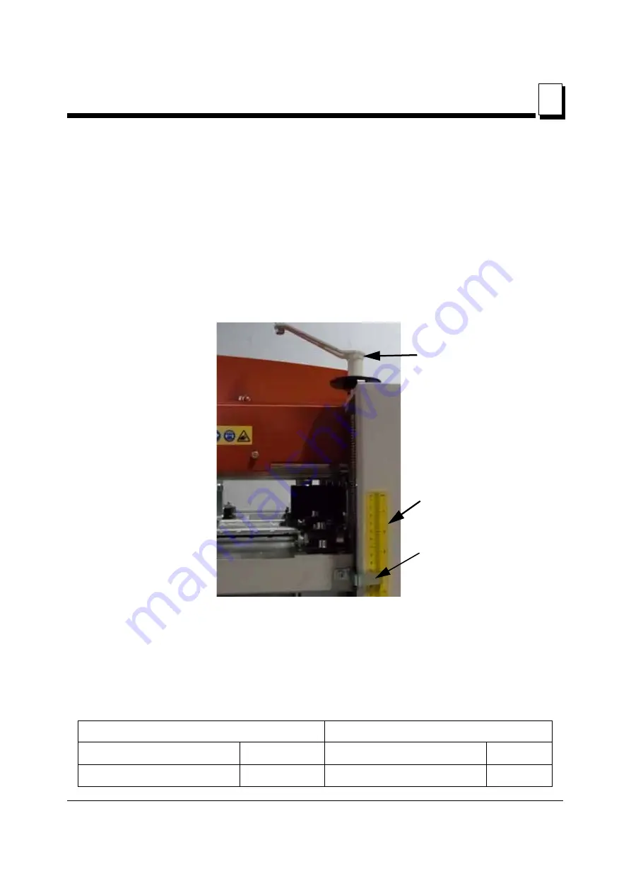
The cutting depth of the upper cutter is adjusted by turning the adjustment crank handle
that raises and lowers the cast iron table in the planer. Each turn of the crank raises or
lowers the machine table 5/32” (4 mm).The scale on the front of the machine indicates the
thickness of the finished material. The scale shows both metric and Imperial measure-
ments.

By loosening the indicator screw  and moving the indicator upwards or downwards, the
scale can be calibrated to match the takeoff of the upper cutter.

See Figure 3-9. 

The depth of cut is determined by the thickness of the rough board before it enters the
planer, less the amount of takeoff from the lower cutter, less the amount of the thickness
of the finished board.

Examples:

FIG. 3-9

Imperial

Metric

Rough lumber thickness 

1-1/16 "

Rough lumber thickness 

26 mm

Takeoff of lower cutter

1/16"

Takeoff of lower cutter 

2 mm

Scale

Adjustment 
handle

Scale Indicator

Summary of Contents for MP260

Page 1: ...nd Maintenance MP260 rev A1 00 Safety is our 1 concern Read and understand all safety information and instructions before operating setting up or maintaining this machine Form 2333 Original Instructio...

Page 2: ...rollers 3 26 3 6 Leveling the machine cast iron table 3 27 3 7 Running the first test board 3 28 SECTION 4 OPERATION 4 1 4 1 Operation 4 1 4 2 Planing tips 4 3 SECTION 5 MAINTENANCE 5 1 5 1 Overview...

Page 3: ...ECTION 6 TROUBLESHOOTING 6 1 6 1 Operation problems 6 1 6 2 Mechanical or electrical problems 6 4 SECTION 7 PLANER MOULDER SPECIFICATIONS 7 1 7 1 Overall dimensions 7 1 7 2 Specifications of the plane...

Page 4: ...r using a forklift or pallet jack with lifting capacity of minimum 600kg When replacing spare parts use only original parts and note that anything electrical must be assembled by a qualified electrici...

Page 5: ...re forbidden The MP260 is a planer moulder that can work four sides of a workpiece in one action The planer moulder is contained in a stable and strong chassis The table is made of planed cast iron Th...

Page 6: ...rew the planer moulder down to the floor if it does not have to be moved Ensure that there is enough space for the longest boards you want to plane at the in and outfeed sides and that there is enough...

Page 7: ...ed wrench 10 mm supplied Wrench 10 mm Ring wrench 13 mm Open ended wrench 30 mm supplied Adjustable wrench 8 or 10 Sliding caliper Measuring tape or ruler Paraffin oil for the table Whetstone FOLLOWIN...

Page 8: ...l rules It is necessary to set the fan so that it will be easy to reach the switch IMPORTANT Remove the chips from the planer moulder when the work is finished CHIP EXTRACTOR TECHNICAL REQUIREMENTS1 T...

Page 9: ...ment Visa Mastercard or Discover COD Prepayment Net 15 with approved credit Be aware that shipping and handling charges may apply Handling charges are based on size and quantity of order In most cases...

Page 10: ...S call us toll free at 1 800 525 8100 Ask to speak with a Customer Service Representative Please have your machine identification number and your customer number ready when you call The Service Repre...

Page 11: ...information NOTE gives helpful information Warning stripes are placed on areas where a single decal would be insufficient To avoid serious injury keep out of the path of any equipment marked with war...

Page 12: ...bility to comply with all applicable federal state and local laws rules and regulations regarding the ownership and operation of your Wood Mizer planer moulder All Wood Mizer planer moulder owners are...

Page 13: ...k that the cutter can rotate freely and that there are no tools in or on the planer moulder before it is started Failure to do so may result in serious injury WARNING Always shut off the motor to stop...

Page 14: ...always in proper working condition Planer moulder operation CAUTION The workplace always should be good illuminated The illumination at the operator s position should be at least 300lx Never use the p...

Page 15: ...side DANGER Planing moulding is possible only in direction shown below Arrow indicates planning direction Never try planing moulding in the opposite direction Use proper maintenance procedures DANGER...

Page 16: ...y Emergency switch should be always in good condition IMPORTANT Planer moulder should not be modified by owner Use only original spare parts Keep safety labels in good condition IMPORTANT Always be su...

Page 17: ...description TABLE 2 0 Label View Label Number Description 096317 CAUTION Carefully read operator s manual before handling the machine Observe instructions and safety rules when operating 099220 Close...

Page 18: ...96316 Electric box opening is possible with the switch in 0 position only 096319 Always disconnect the power cord before opening the electric box 524993 CAUTION Hand injury hazard S12004G Always wear...

Page 19: ...tive ear muffs when operating the planer moulder 501465 Always wear safety boots when operating the planer moulder 512107 1 Always wear safety gloves when operating the planer moulder S20098 Motor rot...

Page 20: ...N 3 SETUP 3 1 MP260 Moulder Assembly Some of the machine components need to be assembled by the user before first usage 1 Operator s panel Mount the operator s panel A using three M8x20 socket head bo...

Page 21: ...porting plate B using existing bolts C Tighten all fasteners by hand Using the adjusting screws D adjust the table so is level and on the same height as the moulder cast iron table double check this w...

Page 22: ...ts is recommended Lock the castors if equipped Indoors the planer moulder can be operated with the sawdust collection system only The planer moulder can not be operated when it is raining snowing and...

Page 23: ...Setup Planer moulder setup Setup doc081920 3 4 3 See figure 3 3 FIG 3 3 MP260 E STOP Operator s position...

Page 24: ...completely stop Failure to do so may result in serious injury or death DANGER Use the inspection window to check cutter rotation direction To do it look at the motor fan when planer moulder is turning...

Page 25: ...adjusting the knives on this machine always turn off the electrical circuit supplying power to the machine Failure to fol low this may result in serious injury or death WARNING Wear gloves when worki...

Page 26: ...lots The head can be fitted with 2 additional straight planer knives or moulding knives in the two empty slots FIG 3 1 Lower Cutter Upper Cutter Diameter 2 13 16 72mm Diameter 2 13 16 72mm Width 11 13...

Page 27: ...ow this may result in serious injury or death IMPORTANT Do not put a straight edge through the machine across the nylon inserts to adjust these knives Use the following procedure to set these knives a...

Page 28: ...ase of carpen ter s square will be pushed out of position If the knife it is positioned too low in the cutter head the planer knife will not make contact and the straight edge will not move at all The...

Page 29: ...knife height by adjusting the two recessed adjustment screws next to the cutter track See Figure 3 5 The knife sides have a recess that allows access to the adjustment screw heads FIG 3 4 FIG 3 5 1 L...

Page 30: ...gib lock bolts are tight tighten the height adjusting screws until they touch bot tom of the indentations of the knives CAUTION If the height adjusting screws are screwed too tight the knife will crac...

Page 31: ...table directly under the cutter head 3 Turn the cutter head so that the block will not press against the knives or the knife slots 4 Turn the crank that adjusts the machine table height front right c...

Page 32: ...remove the knife gib lock bolts 2 Place the aluminum setting block supplied next to one of the knife adjustment screws See Figure 3 7 3 Adjust the knife up or down with the hex wrench until it just ba...

Page 33: ...NOTE Always place the leading edge of the knife against the gib This is true for both straight planing knives and moulding knives in all cutter heads 5 Level the knives as described in Leveling lower...

Page 34: ...e planer table are visible This allows longer knives such as bottom relief knives used for making flooring the abil ity to cut without impacting the spacer plate Various configurations used to remove...

Page 35: ...shows both metric and Imperial measure ments By loosening the indicator screw and moving the indicator upwards or downwards the scale can be calibrated to match the takeoff of the upper cutter See Fi...

Page 36: ...in the machine table IMPORTANT Screwed to the chassis above the machine table on the in feed side there is a limiting plate that when it is turned up side down limits the maximum takeoff of the upper...

Page 37: ...y result in serious injury or death WARNING Wear gloves when working with knives in the machine Failure to follow this may result in serious injury or death CAUTION Check for tools used in the operati...

Page 38: ...ximum 3 15 16 100 mm Rotation Speed 7000 rpm Cutting Depth Maximum 1 3 32 28 mm Specifications of the side cutter heads shipped with the machine Diameter Body 3 1 2 90 mm Height Body 1 9 16 40 mm Plan...

Page 39: ...CUTTER WARNING Wear gloves when working with knives in the machine Failure to follow this may result in serious injury or death See Figure 3 13 Location of the side cutters FIG 3 12 FIG 3 13 Locking n...

Page 40: ...me direction as their respective cutter rotate REPLACING KNIVES 1 Loosen the lock screw with a 4 mm hex key supplied 2 Remove the gib 3 Remove the knife from the dowel pins 4 Insert a new knife and gi...

Page 41: ...at the cutter head can rotate freely and that there is approximately 5 mm 0 2 between the outermost cutting diameter of the cutter and the chip deflector that works as a chip barrier behind the movabl...

Page 42: ...height of the head You may have to try several combinations of shims in order to achieve the correct height setting for the side cutter knives Replace the cutter in the same orientation as it came out...

Page 43: ...ble side cutter head The movable side cutter head has a locking bolt under the table on the output side Loosen the movable side cutter locking bolt by the handle See Figure 3 17 Use the crank on the f...

Page 44: ...just in front of the side cutter and can be moved in or out as needed to allow for varying width boards Where this bracket is placed also determines the widest board the machine will accept The press...

Page 45: ...ain transmission Adjusting the feed roller pressure On each end of the feeding rollers there is a spring mounted bearing housing Under the bearing housing there is a spring on a threaded bar The press...

Page 46: ...have mounted in the machine The feeding speed can be adjusted from 2 m min to 12 m min 3 6 Leveling the machine cast iron table IMPORTANT Leveling the machine table is a complicated operation Ensure...

Page 47: ...ent of the table Adjust this by slightly turning the diffi cult bar even if this results in the table being not completely level This deviation is taken care of by fine tuning the position of the uppe...

Page 48: ...s are started CAUTION Do not adjust the feeding speed if the motor of the feed rollers is not running Equipment damage may occur 4 Slow the speed of the feed rollers down using the knob on the planeta...

Page 49: ...d through the planer through the observation window that is inte grated into the lid 8 Stop the machine with the stop button when the board gets just past the left side cutter just before it comes in...

Page 50: ...re are their locations in the machine SETTING THE SECOND SIDE CUTTER FENCE The second side cutter fence is located on the far side of the stationary cutter see figure 3 23 It is set back away from the...

Page 51: ...f the machine should be clear Material should be placed close to the infeed end of the machine for quick feeding into the machine and a stacking area should be prepared at the outfeed end Once the mac...

Page 52: ...jury or death Read and understand all information and warnings contained in the Safety section of this Operators Manual before starting the planer CONTROL PANEL OPERATION The MP260 is operated via the...

Page 53: ...ll it out until you here a click Check for rotation of all cutter heads before closing the lid and starting the machine Each cutter head should move freely and not impact any fences before starting Ch...

Page 54: ...o not wait the fuse on the brake card may blow or if that fuse fails you will damage the brake card 4 2 Planing tips General recommendations If the knives in the upper cutter protrude too much the las...

Page 55: ...rollers are to be set so that the feed rollers balance on the workpiece If the feed rollers lie diagonally over the workpiece they can pull askew and in addition the grooves in the rollers will make...

Page 56: ...oards as they move through the machine and across the width of the cast iron table Planing stock thicker than 2 Inches The planer can mould and plane stock thicker than two inches with the side heads...

Page 57: ...groove board from this previous run in the machine and match the knife height to match this original board 1 Set the side cutters to the initial height by measuring with straight edges from the cast...

Page 58: ...result in serious injury or death Having a clean and organized work area helps prevent most of the types of accidents that commonly occur in a workshop environment Your work space should have designa...

Page 59: ...the springs under the bearing housings of the feed rollers If so clean them Sometimes the spring must be removed from the threaded bar to be cleaned Note the setting of the spring before removing it...

Page 60: ...doc081920 Maintenance 1 The bearing holders and springs of the feed rollers See Figure 5 1 Total of 10 four steel rollers and one rubber 2 Lubricate the trapezoidal threaded bars See Figure 5 2 Locate...

Page 61: ...oved 4 The carriage of the movable cutter See Figure 5 4 Lubricate position bars and the threaded rod If the movable cutter is set in the same position for a long time e g when producing long series o...

Page 62: ...ain transmission of the feed rollers See Figure 5 5 Cover removed 6 Knives spacers pressure rollers and side rollers See Figure 5 6 5 6 Cleaning the metal feed rollers Pitch may build up on the metal...

Page 63: ...ating fluid properly to avoid spontaneous combustion Failure to follow this will result in serious injury or death IMPORTANT If you are selling your shavings for livestock purposes this may limit the...

Page 64: ...e See Figure 5 7 Outfeed view chain adjustment sprocket lock nut use 17mm wrench See Figure 5 8 View from bottom looking up outfeed side cover panel removed 1 Remove the cover panel by using a 5 mm he...

Page 65: ...reinstall new set screws in the feed roller sprocket the set screw heads must enter the cutouts for them located in the shaft NOTE If the sprocket rotated on the shaft it must be removed and re aligne...

Page 66: ...ks See Figure 5 10 Remove the master link by placing a flat tip screwdriver behind the ends of the C clip apply pressure and carefully push the C clip off of it s mounting points IMPORTANT The C clip...

Page 67: ...the stationary vertical cutter These screws pass through slots in the motor mount and fasten into the cast iron table See Figure 5 11 Use a 6 mm hex wrench to loosen mounting screws one turn 3 Use a 1...

Page 68: ...the cast iron table NOTE The belt must be finessed over the top of the drive motor pul ley and under the bottom of the cutter pulley to come straight out The clearances are tight but it will come out...

Page 69: ...related to the exterior parts of the machine you need to remove to gain access to the belt 1 Remove the movable vertical cutter chip extractor hose mount See Figure 5 13 2 Remove rear cover of the mov...

Page 70: ...rews pass through slots in the motor mount and fasten into the cast iron table 5 Loosen do not remove the belt tension adjustment bolt to remove the tension from the drive belt NOTE The belt tension a...

Page 71: ...the tension adjustment bolt bracket makes contact with the cast iron table NOTE The belt must be finessed over the top of the drive motor pul ley and under the bottom of the cutter pulley to come str...

Page 72: ...w belt and slowly lower the motor with pulley to tighten the belt 5 Tighten the belt properly Do not over tighten the belt Properly tightened belt should be deflected by 1 5cm with a force of 7kg 6 Ch...

Page 73: ...new belt and slowly lower the motor with pulley to tighten the belt 5 Tighten the belt properly Do not over tighten the belt Properly tightened belt should be deflected by 1 5cm with a force of 10 kg...

Page 74: ...ntly sharp will heat up when cutting If you see blackened edges on moulding knives this is an indication that the knives are not sharp Continuing to use these knives will cause excessive wear on the m...

Page 75: ...er cord Perform all routine actions described above Remove the knives with mounting strips or clamping wedges and store them well lubricated in above zero temperature Loosen the motor belt tension Spr...

Page 76: ...nspection Use I buttons to start all cutters and next feed rollers The motors should start Press the E STOP button located on the control box All motors should be stopped Pressing any of I buttons sho...

Page 77: ...l or inadvertent operation when such operation could cause injury to personnel Do not attempt to operate any switch or valve bearing a lock Lockout procedures must be used during Maintenance hazards i...

Page 78: ...tagout may be used provided the owner operator complies with the provisions of the standard which require additional training and more rigorous periodic inspections When tagout is used and the energy...

Page 79: ...tch close valve etc 4 De activate the energy isolating device s so that the machine or equipment is isolated from the energy source s 5 Lock out the energy isolating device s with assigned individual...

Page 80: ...r removed from the area 3 Verify that the controls are in neutral 4 Remove the lockout devices and re energize the machine or equipment NOTE The removal of some forms of blocking may require re energi...

Page 81: ...ure of the feed rollers is incorrectly adjusted 4 The workpiece is bent or warped 5 There is play in the suspension of the machine table 1 Adjust the in and out feed tables so that they are set to the...

Page 82: ...spond to the setting of the scale 1 The takeoff of the knives in the upper cutter are set incorrectly 2 The pointer of the height scale is set incorrectly 1 Set the takeoff of the planing knives to 1...

Page 83: ...ch the first two pressure rollers are mounted and also adjust the pressure roller behind cutter 3 4 Clean and lubricate the spring mecha nisms of the three pressure rollers 5 Choose a wider workpiece...

Page 84: ...ergency stop button by pulling it outwards 3 Check the residual circuit breaker and the fuses in the building Also check the connecting cable 4 Wait until the overheating protection of the motor autom...

Page 85: ...ing Remove wood debris that has got stuck in the springs of the feed rollers 5 Remove the wood debris and increase the air flow in the chip extractor of the upper cutter 6 Clean and lubricate the tabl...

Page 86: ...and that the cooling fans of the motors have free flow If the motors are kept clean they will be cooled more efficiently 2 Grind or replace the knives 3 The electrical system may only be opened by a q...

Page 87: ...ring is defect This can be due to wood debris that has accumulated on the back of the bearing housing which leads to overheating 4 The belt transmission is defect 1 Clean the cutter and mount the kniv...

Page 88: ...nsions 7 7 1 doc081920 PLANER MOULDER SPECIFICATIONS SECTION 7 PLANER MOULDER SPECIFICATIONS 7 1 Overall dimensions See figure 7 1 The overall dimensions of the MP260 Planer moulder are shown below al...

Page 89: ...13S 3 ph 230V CE Standard MP260EB12U 3 ph 230V UL Standard MP260EB13U MP260EB13U V 3 ph 230V UL Standard MP260EC13U MP260EC13U V 3 ph 460V UL Standard MP260EH12S MP260EH13S V 3 ph 400V CE Standard TAB...

Page 90: ...wer 4kW 3kW 3kW 3kW 0 37kW Wood Mizer Part 537387 UL 537386 UL 537385 UL 537385 UL 533640 UL TABLE 7 3 MP260EA12U Upper cutter motor specifica tions Lower cutter motor specifica tions Side fixed cutte...

Page 91: ...vels not necessarily to noise levels in the workplace Although there is a relation between emission levels and exposure levels it is not possible to determine with certainty if preventives are needed...

Page 92: ...h 4 mm Upper cutter max moulding depth 20 mm Lower cutter diameter 72 mm Lower cutter width 300 mm Lower cutter max planning depth 4 mm Lower cutter max moulding depth 10 mm Side cutter diameter 90 mm...

Page 93: ...maximum 1 5 kPa for the nominal air flow rate If the pressure drop exceeds 1 5 kPa the machine might not be compatible with conventional CADES IMPORTANT The dust extractor hoses must be grounded or ma...

Page 94: ...y us this declaration is no longer valid We the undersigned herewith declare that Designation of the machine Four sided planer moulder Wood Mizer MP260 TYPE MP260 Models MP260EH13S V MP260EB13S V MP26...

Reviews: