background image

Alignment

Side Supports

Alignment

15doc091818

6-18

6

6.11 Side Supports

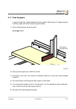
Logs and boards are clamped against the side supports when sawing. The sides supports
must be square to the bed to ensure square lumber.

1.

Place a flat board across the bed rails.

See Figure 6-15. 

2.

Swing a side support up so that it is vertical.

3.

Pull  back  at  the  top  of  the  support  to  eliminate  slack  as  if  a  log  were  being  clamped
against it.

4.

Check the angle of each support with a square on the board.

5.

The side support should be 90° to the bed rails. Turn the adjustment bolt counterclock-
wise to tilt the top of the side support forward.

6.

Repeat for the remaining side supports.

FIG. 6-15

Side Support
Adjustment Bolt

150039

Summary of Contents for LT15 Series

Page 1: ......

Page 2: ......

Page 3: ...v A1 01 LT15M2 G18 rev A1 01 LT15S3 D10 rev A1 01 LT15M2 D10 rev A1 01 Safety is our 1 concern Read and understand all safety information and instructions before operating setting up or maintaining this machine Form 798_af This is the original language for the manual ...

Page 4: ... the day they are ordered Second Day and Next Day shipping are available at additional cost If You Need Service From Europe call our European Headquarters and Manufacturing Facility in Kolo Poland at 48 63 2626000 or 48 3912 1319 From the continental U S call us toll free at 1 800 525 8100 Ask to speak with a Customer Service Representative Please have your vehicle identification number and your c...

Page 5: ...ccess to them 456 A 5 24 1 X H P A F9 017 F9 01 REVISION NUMBER DESCRIPTION Customer No VIN No Revision No A1 Major Revision Code 00 Code Minor Revision Revision Number Company Identification Number 456 Wood Mizer Indiana Weight Class A Under 1361 kg B 1361 1814 kg C 1814 2268 kg D 2269 3000kg Product No 1 LT10 15 2 LT20 Series 4 LT40 Series 7 LT70 Series Length of the Trailer 20 20 Ft 24 24 35 35...

Page 6: ...6 15doc091818 ...

Page 7: ...ce Procedures Keep Safety Labels In Good Condition 1 6 Belt Sizes 1 15 1 7 Blade Sizes 1 15 1 8 Cutting Capacity 1 16 1 9 Engine Motor Specifications 1 16 1 10 Noise Level 1 16 1 11 Dust Extractor Specifications 1 17 1 12 Overall Dimensions 1 18 1 13 Components 1 19 SECTION 2 SAWMILL ASSEMBLY 2 1 2 1 Mounting Parts of LT15 Sawmills with gasoline 2 1 Parts specifications Specifications of Fasteners...

Page 8: ...l 4 1 4 3 Carriage Track Rollers 4 2 4 4 Vertical Mast Rails 4 2 4 5 Miscellaneous Lubrication 4 3 4 6 Blade Wheel Belts 4 4 4 7 Up Down System 4 4 4 8 Miscellaneous Maintenance 4 5 SECTION 5 TROUBLESHOOTING GUIDE 5 1 5 1 Sawing Problems 5 1 SECTION 6 ALIGNMENT 6 1 6 1 Pre Alignment Procedures 6 1 6 2 Preparing The Sawmill For Alignment 6 2 6 3 Blade Installation and Alignment 6 3 6 4 Blade Wheel ...

Page 9: ...ice Representative Please have your machine identification number and your customer number ready when you call The Service Representative can help you with questions about the operation and maintenance of your machine He also can schedule you for a service call Office Hours Please have your vehicle identification number and your customer number ready when you call Wood Mizer will accept these meth...

Page 10: ...SWITZERLAND Stefan Wespi Maschinen u Geräte Spezialarbeiten GmbH Eichistraße 4 6353 Weggis Tel 41 0 41 3900312 GSM 41 0 79 9643594 info mobilsaegen ch RUSSIA Dariusz Mikołajewski OOO WOOD MIZER INDUSTRIES 141031 Moscow Reg Mytishenski raj pos Veshki Zavodskaja str 3B Tel Fax 7 495 788 72 35 Tel Fax 7 495 641 51 60 e mail dariuszm woodmizer moscow ru BULGARIA Kalin Simeonov Ecotechproduct 38 Star L...

Page 11: ... Kerestecilik San ve Tic Ltd Sti Adana Keresteciler Sitesi 191 sk No 41 ADANA Tel 90 322 346 15 86 Fax 90 322 345 17 07 GSM 90 533 363 18 44 e mail info erkaahsap com tr FINLAND Howard Blackbourn Oy Falkberg Jordbruk Ab Falkintie 220 25610 Ylonkyla Tel 358 2732 2253 Fax 358 2732 2263 Howard Blackbourn GSM 358 440 424 339 e mail falkberg woodmizer fi LITHUANIA Andrius Zuzevicius UAB Singlis Savanor...

Page 12: ...1 55312 2042 e mail Info dragtbosbouw nl Subagent ROMANIA M Echert S C Echert Comprod s r l Str Schitului Nr 6 Apt 7 etajul 1 725 70 Vatra Dornei Romania Tel Fax 40 230 374 235 Tel 40 740 35 35 74 Regional Manager Africa Wood Mizer Africa Jean Jacques Oelofse UNIT 3 LEADER PARK NO 20 CHARIOT ROAD STORMILL EXT 5 Roodepoort Johannesburg Tel 27 011 473 1313 Fax 27 011 473 2005 Jean Jacques Oelofse E ...

Page 13: ...dangers warnings and cautions Always be sure that all safety decals are clean and readable Replace all damaged safety decals to prevent personal injury or damage to the equipment Contact your local distributor or call your Customer Service Representative to order more decals IMPORTANT It is always the owner s responsibility to comply with all applicable federal state and local laws rules and regul...

Page 14: ...re in place and secured before operating or towing the sawmill Failure to do so may result in serious injury DANGER Be sure the blade housing and pulley covers are in place and secured DANGER Always keep hands away from moving bandsaw blade Failure to do so will result in serious injury DANGER Keep all persons out of the path of moving equipment and logs when operating sawmill or loading and turni...

Page 15: ...e CAUTION Do not try to force the saw head beyond its upper and lower travel limits Damage to the up down system may result CAUTION Be sure to stop the blade when returning the carriage This will not only prevent the blade from being pulled off and ruined by a wood sliver but also will increase the life of the blade CAUTION Never clean the blade or the blade wheels with a brush or a scraper during...

Page 16: ...the wiper presses too firmly against the bar it can cause the power feed to bind CAUTION Never use grease on the mast rails as it will collect sawdust Always be sure that all safety decals are clean and readable Replace all damaged safety decals to prevent personal injury or damage to the equipment Contact your local distributor or call your Customer Service Representative to order more decals ...

Page 17: ...e entire Operator s Manual before operating the sawmill Take notice of all safety warnings throughout this manual and those posted on the machine Keep this manual with this machine at all times regardless of ownership Also read any additional manufacturer s manuals and observe any applicable safety instructions including dangers warnings and cautions Only adult persons who have read and understood...

Page 18: ...rson Keep all other persons away from area when coiling carrying or changing a blade Failure to do so may result in serious injury WARNING Always wear eye ear respiration and foot protection when operating or servicing the sawmill Keep sawmill And Area Around sawmill Clean DANGER Maintain a clean and clear path for all necessary movement around the sawmill and lumber stacking areas Failure to do s...

Page 19: ...t in serious injury Keep Persons Away DANGER Keep all persons out of the path of moving equipment and lumber when operating the sawmill Failure to do so will result in serious injury DANGER Always be sure all persons are out of the path of the blade before starting the motor Failure to do so will result in serious injury WARNING Allow blade to come to a complete stop before opening the blade housi...

Page 20: ... a hot motor Allow the motor to cool sufficiently before beginning any service function DANGER Always keep hands away from moving bandsaw blade Failure to do so will result in serious injury DANGER Always be aware of and take proper protective measures against rotating shafts pulleys fans etc Always stay a safe distance from rotating members and make sure that loose clothing or long hair does not ...

Page 21: ...of another person that the power is off check it out and lock it out WARNING Do not wear rings watches or other jewelry while working around an open electrical circuit WARNING Remove the blade before performing any service to the motor or sawmill Failure to do so may result in serious injury DANGER Never clean the blade or blade wheels using the hand held brush or scraper whilst the sawmill blade ...

Page 22: ...ure that all safety decals are clean and readable Replace all damaged safety decals to prevent personal injury or damage to the equipment Contact your local distributor or call your Customer Service Representative to order more decals IMPORTANT If replacing a component which has a safety decal affixed to it make sure the new component also has the safety decal affixed ...

Page 23: ...E 1 1 Decal View W M No Description 096317 CAUTION Read thoroughly the manual before operating the machine Observe all safety instructions and rules when operating the sawmill 099220 CAUTION Close all guards and covers before starting the machine 099219 Blade tension Turning the bolt clockwise will increase the blade tension and turning the bolt counterclockwise will decrease the tension 099220 09...

Page 24: ...818 Safety General Information 099221 CAUTION Keep all persons a safe distance away from work area when operating the machine 086099 CAUTION Hot elements keep your distance 098176 CAUTION Keep away from debarker blade 096321 Blade movement direction TABLE 1 1 099221 086099 098176 ...

Page 25: ...818 1 13 1 S12004G CAUTION Always wear safety goggles when operating the sawmill S12005G CAUTION Always wear protective ear muffs when operating the sawmill 501465 CAUTION Always wear safety boots when operating the sawmill 501467 Lubrication point P11789 PL Aligning the blade on the wheels TABLE 1 1 ...

Page 26: ...c091818 Safety General Information 510643 Setting the blade tension indicator P85070 CE safety certification 099401 Russian safety certification S20097A 3600 RPM engine rotation direction TABLE 1 1 70 75 510643 75 80 80 85 1015 1088 1088 1160 1160 1233 099401 S20097A 3600 RPM ...

Page 27: ...97448 Blade Pulley Belts B57 1 1 To insure proper blade tracking use Goodyear Dayco Super II or Browning belts only P04185 TABLE 1 2 Engine Motor Size Recommended Blade For Sawing 1 1 The LT15 sawmill is equipped with a blade having a length of 4 01 m Softwood Hardwood Frozen or Hard to Cut Wood 5 hp 15hp B275IH1030 B275IH741030 B375IH929 B375IH929 2 2 TRU SHARP F blades use a 9 29 profile 9 hook ...

Page 28: ...406 ccm 3600 min 1 TABLE 1 5 Sawmill Noise Level LT15E11 81 9 dB A LT15G18 89 7 dB A LT15D10 87 0 dB A TABLE 1 6 1 The noise level measurement was taken in accordance with PN EN ISO 3746 Standard The noise exposure level given above concerns an 8 hour work day Value for associated uncertainty K 4dB 2 The figures quoted are emission levels and are not necessarily safe working levels Whilst there is...

Page 29: ...e highest root mean square value of weighted acceleration to which the whole operator s body is subjected does not exceed 0 5 m s2 Airflow 1200 m3 h 3937ft3 h Inlet diameter 100 mm 5 9 Motor power 1 5 kW Number of sacks 1 pc Sack capacity 0 25 m3 8 8 ft 3 Weight 110 kg 242 5 lb Pressure drop 1 5 kPa 0 22 psi 1 1 The pressure drop between the inlet of the capture device and the connection to the CA...

Page 30: ...imensions 1 1 18 15doc091818 Safety General Information 1 12 Overall Dimensions See Figure 1 2 The overall dimensions of the LT15 sawmills are shown below FIG 1 1 1790 2026 2700 2700 6750 675 675 1950 1950 1950 7200 LT15M2 LT15S3 15B001F ...

Page 31: ...the operator s position 1 13 Components The major components of the Wood Mizer LT15G18 are shown below FIG 1 2 FIG 1 3 150189a 150170_G LT15G18_Manual_Oper Water Tank Bed Rail Engine Saw Head Bed Frame Blade Tension Handle Log Clamp Up Down Feed Crank Handle Blade Guide Arm Lever Blade Guide Battery Box Up Down Drive Motor ...

Page 32: ... M3 Qty LT15 S2 Qty LT15 S3 S3 P Qty LT15 S4 S4 P LT15 S3 LT15 S3 P LT15 S4 LT15 S4 P 095250 LT15DC Sawmill Saw Head 1 1 1 1 1 1 1 094697 LT15 Bed Section Complete 2 75 m 2 3 094514 LT15 Bed Section Complete 1 95 m 2 3 3 4 4 085981 1 Thick Spacer Washer 4 6 4 6 6 8 8 085982 1 Log Side Support Complete 4 6 4 6 6 8 8 085994 1 Bed Leg Mounting Washer Painted 12 18 8 12 12 16 16 510720 1 Leveling Wedg...

Page 33: ...1 Frame Mounting Strap Zinc plated 3 4 3 4 4 6 6 086745 Middle Track Cover with Felt Wiper 1 1 1 1 1 092378 1 Bracket Blade Guide Roller Guard 1 092379 1 Blade Guide Roller Guard 1 093859 Plate PC Guard 1 1 1 1 1 094250 1 Track Rail Zinc plated Short 2 2 2 2 2 2 2 095490 1 Auxiliary Bed Rail 1 1 1 1 1 1 1 100903 1 Sawdust Chute 1 1 1 1 1 500844 1 Bed Extension Tube Painted 2 2 2 2 2 2 2 Table 1 ...

Page 34: ... BED SECTION CONNECT OR 8 12 8 12 12 16 12 507565 Log Clamp 2 3 2 3 3 4 4 508236 1 Feed Rope Mount Front Bracket LT15 EC 1 508237 1 Feed Rope Mount Rear Bracket LT15 EC 1 094427 1 LT15S3 094696 1 LT15M2 Track Rail 2 3 2 3 3 4 4 LTBGAT Tool Blade Guide Alignment R02080 Rope 8 7 9 7 9 12 Vertical Mast Lock Assembly 086743 1 Zinc plated Pin 2 2 2 2 2 F81045 1 Roll Pin 6x50 2 2 2 2 2 Table 1 ...

Page 35: ... Pin S Zn 4x25 2 2 2 2 2 2 2 F81058 1 FlatWasher 17 2 2 2 2 2 Manaual Feed Assembly 506427 1 Power Feed Crank Handle 1 1 1 1 094142 Bushing 2 2 2 2 086338 Crank Handle Grip 1 1 1 1 F81033 1 Hex Nylon Lock Nut M10 1 1 1 1 Power Feed Assembly R80663 Rope 9 9 4 500839 Track Cover w Felt Wiper 1 1 500726 Cover LT15 Lower 1 1 501417 1 Link Power Feed System Rope 2 2 Table 1 ...

Page 36: ...port 2 2 500848 1 Tensioner Short 1 1 500846 1 Tensioner 1 1 089689 Spring Press Roller 1 1 086182 1 Mount Wdmt Carriage Stop 2 2 P12165 Bushing Rubber 2 2 091614 Clamp Rope 4 4 Outrigger Leg Kit Option 095745 1 Leg Mounting Block 12 18 8 12 12 16 16 087771 1 LT15 Foot Mount Plate 12 18 8 12 12 16 16 Table 1 ...

Page 37: ...2 F81001 7 M6x12 Bolt 2 2 F81002 20 M8x16 Bolt 2 2 2 2 F81002 4 M8x20 Bolt 8 8 8 8 8 8 8 F81002 5 M8x25 Bolt 3 3 3 3 3 3 3 F81002 6 M8x12 Bolt 2 2 F81003 1 M10x20 Bolt 6 2 2 2 2 F81003 11 Bolt M10x25 8 8 6 8 8 8 8 12 12 F81003 15 M10x75 Bolt 34 47 27 34 34 43 43 F81003 2 M10x30 Bolt 5 8 4 4 4 4 4 4 4 F81003 2 M10x30 Bolt 8 8 4 12 4 F81003 66 M10x90 Bolt 1 1 1 1 1 1 1 F81004 12 Bolt M12 55 8 8 F810...

Page 38: ...1 6 5 Special Flat Washer 6 6 F81054 1 8 4 Flat Washer 16 16 16 16 16 16 16 F81054 4 Washer 8 4 Flat zinc F81055 1 10 5 Flat Washer 100 150 101 101 106 126 131 F81055 2 10 2 Split Lock Washer 10 12 12 12 12 16 16 F81056 1 13 Flat Washer 26 38 30 36 36 46 46 Outrigger Leg Kit Option F81003 58 M10x120 Bolt 24 36 16 24 24 32 32 F81007 1 M20x240 Bolt 12 18 8 12 12 16 16 F81037 1 M20 Nut 12 18 8 12 12 ...

Page 39: ...SEMBLY 15doc091818 2 8 2 2 1 3 Tools Necessary for Assembling the Sawmill Tabela 3 Required Tools Flat Wrench 8 1pcs Flat Wrench 10 2pcs Flat Wrench 13 2pcs Flat Wrench 17 2pcs Flat Wrench 19 2pcs Ratchet Wrench 30 1pcs Hammer 1pcs Allen Wrench 4 1pcs Allen Wrench 5 1pcs ...

Page 40: ...s arranged inside the bed section 3 Using a forklift truck or a winch with lifting capacity of minimum 500 kg carefully lift the saw head and set it aside Then attach the winch hook to the bracket on the saw head WARNING When removing the saw head use extreme care and keep all persons at a safe distance Failure to do so may result in serious injury or death FIG 2 1 ...

Page 41: ...SAWMILL ASSEMBLY Unpacking the Sawmill SAWMILL ASSEMBLY 15doc091818 2 10 2 See Figure 2 2 FIG 2 2 ...

Page 42: ... screw joints without split lock washer or lock nylon nut use the LOCTITE 243 blue of average durability for screw joints 1 Mount preliminarily the track rail as shown in Figure 2 3 Do not tighten the nuts See Figure 2 3 FIG 2 3 150158b M10x75 Bolt M10 Hex Nylon Lock Nut 10 5 Washer 094427 1 LT15S3 094696 1 LT15M2 ...

Page 43: ...each bed section Use two hex head bolts and lock nuts to secure each leg bracket to the bed section Be sure the nut on the bracket faces up Thread a leg into each bracket See Figure 2 4 FIG 2 4 150160a M10x120 Bolt 085994 1 086723 1 M10 Hex Nylon Lock Nut 10 5 Washer 095745 1 095742 1 M20 Nut 21 Washer ...

Page 44: ...and nylon lock nuts See Figure 2 5 4 Fasten the track rails together using the frame mounting straps on the outside of the frame See the figure above Secure each strap to the track rail with two hex head bolts Tighten the track rail mounting nuts FIG 2 5 10 2 Split Lock Washer M10x25 Bolt Frame Mounting Strap 086660 M12 Hex Nylon Lock Nut 13 Flat Washer M12x120 Bolt 4pcs M10x30 Bolt 4pcs 10 5 Flat...

Page 45: ...the rear ends of the bed frame See Figure 2 6 6 Assemble a log clamp to a bed rail on each bed section using the existing hex head bolts and nylon lock nuts FIG 2 6 M10 Hex Nylon Lock Nut 13 Flat Washer M10x75 Bolt 10 5 Washer 094250 1 M12x120 Bolt 086659 1 M10x25 Bolt 10 2 Split Lock Washer M12 Hex Nylon Lock Nut ...

Page 46: ...Y 7 Install the log side supports as shown in Figure 2 7 Tighten the nuts so that the side supports can be moved with little resistance Adjust the side supports See Section 6 11 See Figure 2 7 FIG 2 7 M10 M12x140 Bolt 100076 1 Bolt M12 Nut 13 Washer 097224 085981 1 014972 ...

Page 47: ...stment 1 Place a foot plate under each bed leg 2 Using an appropriate wrench adjust each leg so that the nut is approximately 25mm below the top of the bed tube See Figure 2 8 CAUTION The top of the leg should not be higher than the top surface of the bed rail FIG 2 8 25mm 1 150108b Foot Plate ...

Page 48: ... serious injury or death 2 Position the middle track cover between the two track roller housings so the opening in the cover is positioned over the feed rope pulleys Secure with two hex head bolts and lock washers 3 Install a track wiper with a felt strip to each track roller housing using a 8 4 flat washer and M8x12 hex head bolt See Figure 2 9 4 Assemble the retaining bracket to the idle side up...

Page 49: ...Y Saw Head Assembly SAWMILL ASSEMBLY 15doc091818 2 18 2 strips with lubricating fluid e g Mineral Oil 6 Assemble mast safety pins See Figure 2 10 FIG 2 10 Pin 086743 1 Spring 087301 Cotter Pin F81043 2 Washer F81058 1 ...

Page 50: ...SAWMILL ASSEMBLY Saw Head Assembly 2 2 19 15doc091818 SAWMILL ASSEMBLY 7 Install the PC operator guard See Figure 2 11 FIG 2 11 10 5 Washer M10x50 Bolt M8x16 Bolt 8 4 Washer ...

Page 51: ...sembly SAWMILL ASSEMBLY 15doc091818 2 20 2 8 Install the blade guides See Figure 2 12 9 Adjust the saw head stop bolt See Section step 14 FIG 2 12 M10x1x20 Screw 7 Blade Guide 094682 M10x1x25 Bolt M10x1 8 Washer Blade Guide 094683 ...

Page 52: ...angled toward the end of the frame at which it is mounted as shown below See Figure 2 13 2 Tie a knot in one end of the feed rope Slip the knotted end of the rope into the front rope mount bracket Route the rope between the saw head and main bed frame tube FIG 2 13 150110F M10x30 Bolt Front Rope Mount Bracket 502725 1 10 5 Flat Washer Rear Rope Mount Bracket 502726 1 M10x30 Bolt 10 2 Split Washer ...

Page 53: ... See Figure 2 14 3 Loop the rope around the inner groove of the lower v groove roller and route to the feed crank spool See Figure 2 15 4 Loop the rope around the feed crank spool three times and route back down to the outer v groove roller FIG 2 14 FIG 2 15 15B007d 150111 ...

Page 54: ...SAWMILL ASSEMBLY Feed Rope Assembly 2 2 23 15doc091818 SAWMILL ASSEMBLY See Figure 2 16 FIG 2 16 150112 ...

Page 55: ...nd the outer groove of the v groove roller See Figure 2 17 6 Route the rope to the rear mounting bracket Tie a knot in the end of the rope and insert into the mounting bracket Position the knot in the rope so when installed to the rear bracket the rope is tight FIG 2 17 FIG 2 17 150113 150011B ...

Page 56: ...t of mounting holes provided between the two bed rails Remove the existing bolt and lock nut that secures the track at this position Use three hex head bolts and lock nuts to secure the bed rail to the bed section Replace the track mounting bolt and lock nut See Figure 2 18 FIG 2 18 Auxiliary Bed Rail 095490 1 M10x75 Bolt 3 M10x80 Bolt 1 M10 Nut 4 10 5 Washer 8 ...

Page 57: ...log loading ramp mount ramp bracket 1 to the bed frame section tube using two bolts 2 four washers 3 and two nuts 4 in place shown below Insert ramp assembly 5 into ramp bracket 1 See Figure 2 19 1 See Parts List for detailed information about part numbers and mounting hardware dimensions RYS 2 19 1 2 3 3 4 150232a 5 ...

Page 58: ...egs if necessary 2 Run a string from the front bed rail to the rear bed rail near the operator s side of the frame Place identical spacers between the string and the front and rear bed rails Measure the distance between the string and the other bed rails Adjust the frame legs until all bed rails measure the same distance from the string 3 Loosen the auxiliary bed rail bolts and adjust the rail so ...

Page 59: ...tom of the blade near the inside blade guide 8 Measure the distance from the bed rail to the bottom of the blade near the outside blade guide See Figure 3 2 When the blade is parallel to the bed it will measure the same distance from the bed rail at the inside and outside of the saw head To adjust the saw head tilt loosen the four mounting bolts of the idle side roller bracket the two scraper moun...

Page 60: ...t Use the adjustment nuts shown below to adjust the slide pads if necessary 10 Check the vertical alignment of each blade wheel using the blade guide alignment tool Attach the tool to the blade near the outer blade guide Be sure the tool does not rest on a tooth or burr and is lying flat on the blade FIG 3 2 Slide Pad Adjustment Nuts 4 ...

Page 61: ...e bed rail Again measure from the bottom of the tool to the bed rail If the two measurements differ by more than 1 16 1 5 mm adjust the vertical tilt of the idle side blade wheel See Figure 3 4 Remove the tool from the blade and reattach it near the inner blade guide Measure from the tool to the bed rail at both ends of the tool If the measurements at the front and rear ends of the tool differ by ...

Page 62: ...he top adjustment screw and tighten the screw Tighten the top and bottom nuts To tilt the wheel down loosen the top adjustment screw 1 2 turn Loosen the nut on the bottom adjustment screw and tighten the screw Tighten the top and bottom nuts FIG 3 4 To tilt wheel up tighten top screw loosening ealier bottom screw To tilt wheel down tighten bottom screw loosening ealier top screw ...

Page 63: ... Tighten the top and bottom nuts To tilt the wheel up loosen the bottom adjustment screw loosen the nut on the top adjustment screw and tighten the top screw Tighten the top and bottom nuts Recheck the vertical alignment of each blade wheel Readjust if necessary FIG 3 5 150075 1d To tilt wheel up tighten top screw loosening ealier bottom screw To tilt wheel down tighten bottom screw loosening eali...

Page 64: ...uides in the vertical plane and make the final adjustments to the blade deflection The proper blade deflection is 6 mm After adjusting the blade deflection recheck the vertical alignment of the blade guides and adjust if necessary 14 Install the blade height scale To do that first measure the distance from the bottom edge on a down set tooth of the blade to the top of the bed rail Then stick the b...

Page 65: ...Setup Operation Sawmill Setup Setup Operation 15doc091818 3 8 3 16 Bolt the blade guide guard so that its bottom edge is about 25 mm above the blade FIG 3 6 Loosen the nut and adjust the stop bolt ...

Page 66: ...rs that cover the blade wheels Turn the blade tension handle to release the blade tension until the wheel is pulled in and the blade is lying loose in the blade housing Lift the blade out of the blade housing When installing a blade make sure the teeth are pointing the correct direction The teeth should be pointing toward the operator side of the mill when you are looking at the blade below the bl...

Page 67: ...til the tension gauge indicates the recommended tension Check the blade tension occasionally when adjusting the cant control or while cutting As the blade and belts heat up and stretch the blade tension will change Also ambient temperature changes can cause tension to change FIG 3 7 10_074b Blade Tensioner Handle Cant Control Bolt Blade Tension Indicator ...

Page 68: ...n the clutch handle rotating the blade until the blade positions itself on the wheels WARNING Do not spin the blade wheels by hand Spinning the blade wheels by hand may result in serious injury 4 Release the clutch handle to stop the blade Turn off the engine and check the position of the blade on the blade wheels See Figure 3 8 Position 1 1 4 wide blades so the gullet is 1 8 3 0 mm out from the B...

Page 69: ...Setup Operation Tracking The Blade Setup Operation 15doc091818 3 12 3 edge of the blade wheel 1 32 75 mm FIG 3 8 1 5 0 0 6 0 1 1 4 B l a d e 1 m m 3 6 4 3 0 m m 1 8 ...

Page 70: ...istance from the front edge of the wheel 5 Adjust the blade tension if necessary to compensate for any changes that may have occured while adjusting the cant control 6 Close the blade housing covers DANGER Make sure all guards and covers are in place and secured before operating the sawmill Failure to do so may result in serious injury Be sure the blade housing and pulley covers are in place and s...

Page 71: ...n the power socket electric box Setting the phases in the phase inverter correctly will ensure correct rotation directions of all sawmill motors DANGER Make sure all guards and covers are in place and secured before operating the sawmill Failure to do so may result in serious injury Be sure the blade housing and pulley covers are in place and secure DANGER Always be sure the blade is disengaged an...

Page 72: ...n machine damage 3 Raise the side supports on the sawmill bed to prevent the log from falling off the side of the bed 4 Position the log at the foot of the ramps 5 Use a cant hook to roll the log up the ramps and onto the sawmill bed Position the log against the side supports 6 Remove the log ramps and set aside CAUTION The saw head will hit the spring loaded ramp stops when adjusted for low cuts ...

Page 73: ...down so they are below your first few cuts Turn the clamps screws in so they move the log firmly against the side supports See Figure 3 10 2 Be sure to leave crank in the bottom position to avoid damage to the blade See Figure 3 11 3 Make sure the side supports are positioned low enough for the blade to pass over them If FIG 3 10 FIG 3 11 sm0379_A ...

Page 74: ...tion Loading Turning And Clamping Logs 3 3 17 15doc091818 Setup Operation they are not back the clamps off slightly and push the side supports down until they are positioned below the level of your first few cuts ...

Page 75: ...apered Log Use shims or the optional wedge to raise either end of a tapered log if desired Shim one end of the log until the heart of the log measures the same distance from the bed rails at each end of the log FIG 3 12 Level log so heart is same distance from bed rails at both ends Leveling Wedge ...

Page 76: ...ounterclockwise until it disengages the up down shaft 3 Pull back on the crank handle to engage the locking pins for up down operation 4 Turn the up down crank clockwise to raise the saw head counterclockwise to lower the saw head 5 Turn the up down lock clockwise until it engages the up down shaft CAUTION DO NOT try to force the carriage above the 27 68 cm mark or below the 1 2 54 cm mark Damage ...

Page 77: ...guide should be adjusted to clear the widest section of the log by less than 1 25 4 mm 2 Use the blade guide arm handle to adjust the outer blade guide as necessary Move the blade guide arm handle right to move the arm out Move the handle left to move the arm in See Figure 3 14 FIG 3 14 150120B Move the handle right to move the blade arm out Move it left to move the blade guide in ...

Page 78: ...re starting the engine or motor Use the rubber latches to fasten blade housing covers shut If the blade housing covers are not closed and secured hte safety shut off switches interrupt the ignition the contactor circuit and the engine motor can not be started If the cover is opened during the mill operation the engine motor will be stopped Gas diesel engine 1 Clear any loose objects from the area ...

Page 79: ...urn the tensioner handle counterclockwise until it locks in the up position This engages the drive mechanism and increases the engine speed to full throttle 5 To disengage the blade turn the tensioner handle to the down position This disengages the drive belt and returns the engine to idle FIG 3 15 15B026 2a Turn clutch handle counterclockwise to engage blade ...

Page 80: ...low speed This stops the blade from flexing and dipping up or down Use a slow speed until the whole width of the blade has entered the cut Then increase the feed rate as desired Maximum feed rate varies with width and hardness of the wood Over feeding results in engine and blade wear and also produces a wavy cut 2 To move the carriage backward rotate the feed crank counterclockwise or pull the saw...

Page 81: ... do this Set the blade to the desired height with the up down crank Make sure that the blade will clear all side supports and the clamp Adjust the outer blade guide to clear the widest section of the log by moving the blade guide arm knob 3 Make sure all covers and guards are in place Start the engine Engage the clutch lever to start the blade spinning 4 Start the water lube if necessary to preven...

Page 82: ...g was turned 90 degrees and you are using the wedge to compensate for taper in the log use the wedge again to adjust the heart of the log parallel with the bed 10 Repeat the steps used to cut the first side of the log until the log is square Cut boards from the remaining cant by adjusting the blade height for the thickness of boards that you want Example Remember that the blade cuts a 1 16 1 8 1 6...

Page 83: ...ide supports halfway up the flitch height Wider flitches should be placed to the clamp side When they are edged flip them over to edge the second side without disturbing the other flitches or without having to pull them from the middle of the stack 4 Adjust the blade height to edge a few of the widest boards 5 Loosen the clamps and turn the edged boards over to edge the other side 6 Repeat steps 2...

Page 84: ...he blade height indicator shows how many inches the bottom of the blade is above the bed of the mill If you know the height of your blade at each cut you can determine the thickness of lumber you are sawing Example You want to cut 1 25 mm random width boards from a log Position the blade for the first cut Move the carriage to an even measurement on the inch scale Make a trim cut Return the carriag...

Page 85: ... gallon 18 9 liter bottle through a hose to the blade guide where the blade enters the log A valve in the bottle cap controls the amount of water flow See Figure 3 18 Install the water bottle bracket at the top of the saw head mast if the bracket was not already welded to the saw head mast FIG 3 18 Place bottle assembly in bracket Connect hose to blade guide tube 150029 ...

Page 86: ...h sap content WARNING Use ONLY water with the water lube accessory Never use flammable fuels or liquids If these types of liquids are necessary to clean the blade remove it and clean with a rag Failure to do so may result in serious injury or death Before removing the blade engage the clutch brake lever Let the blade spin with water running on it for about 15 seconds This will clean the blade of s...

Page 87: ...ing loaded 2 Move the saw carriage to one end of the frame Engage the travel lock pin to prevent the saw carriage from moving Pull the pin and rotate and release so the roll pin seats in the locking position notch See Figure 3 20 3 Remove the leg assemblies or adjust them above the bottom of the bed frames 4 Position the bed of the truck at the end of the frame opposite the saw head 5 While two pe...

Page 88: ...travel lock pin in the end of the frame in the truck bed 7 Use two people to lift the end of the mill still on the ground and slide the sawmill into the truck bed WARNING Keep all persons out of the path of the saw head while loading and unloading the sawmill Failure to do so may result in serious injury or death 8 Secure the sawmill to the truck bed to prevent the sawmill from shifting while it i...

Page 89: ...PROCEDURE MANUAL REFERENCE EVERY BLADE CHANGE Check blade guide roller performance SEE SECTION 4 2 Remove excess sawdust from blade wheel housings and sawdust chute SEE SECTION 4 2 EVERY 8 HOURS OF OPERATION Clean and lubricate track SEE SECTION 4 3 Remove sawdust from track roller housings SEE SECTION 4 3 f manuals forms 749 15doc091818 ...

Page 90: ...st See Section 4 4 Check blade wheel belts for wear See Section 4 6 Lubricate blade tensioner screw See Section 4 5 WOOD MIZER LT15SC LX100 LX450 MAINTENANCE LOG Check Engine And Option Manuals For Additional Maintenance Procedures PROCEDURE MANUAL REFERENCE TOTAL HOURS OF OPERATION FILL IN THE DATE AND THE MACHINE HOURS AS YOU PERFORM EACH PROCEDURE A SHADED BOX INDICATES MAINTENANCE IS NOT NEEDE...

Page 91: ...ast See Section 4 4 Check blade wheel belts for wear See Section 4 6 Lubricate blade tensioner screw See Section 4 5 WOOD MIZER LT15SC LX100 MAINTENANCE LOG Check Engine And Option Manuals For Additional Maintenance Procedures PROCEDURE MANUAL REFERENCE TOTAL HOURS OF OPERATION FILL IN THE DATE AND THE MACHINE HOURS AS YOU PERFORM EACH PROCEDURE A SHADED BOX INDICATES MAINTENANCE IS NOT NEEDED AT ...

Page 92: ...4 4 Check blade wheel belts for wear See Section 4 6 Lubricate blade tensioner screw See Section 4 5 WOOD MIZER LT15SC LX100 MAINTENANCE LOG Check Engine And Option Manuals For Additional Maintenance Procedures PROCEDURE MANUAL REFERENCE TOTAL HOURS OF OPERATION FILL IN THE DATE AND THE MACHINE HOURS AS YOU PERFORM EACH PROCEDURE A SHADED BOX INDICATES MAINTENANCE IS NOT NEEDED AT THIS TIME 2550 H...

Page 93: ...each maintenance pro cedure should be performed Be sure to refer to option and engine manuals for other maintenance procedures 4 1 Wear Life See Table 4 1 This chart lists estimated life expectancy of common replacement parts if proper maintenance and operation procedures are followed Due to the many variables which exist during sawmill operation actual part life may vary significantly This inform...

Page 94: ...ller housings Remove the track roller housing covers and brush any sawdust buildup from the housings 4 4 Vertical Mast Rails Clean and lubricate the vertical mast rails every 50 hours of operation Clean with solvent and remove any rust with a light grade sand paper or emery cloth Lubricate the mast with motor oil or automatic transmission fluid ATF CAUTION Never use grease on the mast rails as it ...

Page 95: ...us Lubrication 1 Oil all chains with Dexron III ATF every fifty hours of operation CAUTION Do not use chain lube It causes sawdust buildup in chain links 2 Lubricate the tensioner screw with a NLGI No 2 grade lithium grease as needed See Figure 4 2 FIG 4 2 50 Grease Tensioner Threads ...

Page 96: ...p down chain tension as needed Measure chain tension with the head all the way to the top of the vertical mast Secure the carriage with a chain at the top or shim it underneath Find the chain adjusting bolt at the bottom of the mast Loosen the nut on the bolt and move the sprocket down until there is about 1 2 5 cm total deflection in the center of the chain with a 5 lb 2 3 Kg deflection force WAR...

Page 97: ...or or Engine Option manual supplied with your mill for specific adjustment instruc tions 2 Check the mill alignment every setup See Section 6 Alignment 3 If the clutch begins to slip adjust the turnbuckle linkage Turn the turnbuckle clockwise as viewed from the top to provide 46 lbs of tension 4 Make sure all safety warning decals are readable Remove sawdust and dirt Replace any damaged or unreada...

Page 98: ...is being sharpened completely See Sharpener Manual Blades Break Prematurely Rubber belts on blade wheels worn to a point that blade con tacts metal pulley look for shiny spots on edge of wheels Change blade wheel belts B 57 Poor sharpening techniques See Sharpener Manual Tension too tight Tension blade to recom mended specifications Blade Does Not Track Right on Drive Wheel Cant adjustment is inco...

Page 99: ...rack surface Up down chain improperly adjusted Adjust up down chain Vertical wear pads are too tight Adjust pads Lumber Is Not Square Vertical side supports not square to bed Adjust side supports Blade not parallel to bed rails Adjust bed rails parallel to blade Sawdust or bark between cant and bed rails Remove particles Tooth set problems Resharpen and reset blade Sawdust Builds Up On Track Exces...

Page 100: ...Sawmill alignment determines the accuracy and squareness of your cuts The sawmill alignment steps are 1 Ready the sawmill for alignment 2 Adjust the blade parallel to the bed rails 3 Adjust the blade guide arm parallel to the saw head brace 4 Align blade guides to the blade 5 Adjust side supports square to the bed 6 Final Adjustments To insure accurate alignment the sawmill frame must be level and...

Page 101: ...nt Alignment 15doc091818 6 2 6 6 2 Preparing The Sawmill For Alignment Before performing the following alignment procedures setup the mill on firm level ground String the bed and adjust the legs so the frame is level as described in Section 3 1 ...

Page 102: ...n serious injury 4 Release the clutch handle to stop the blade Turn off the engine remove the key and check the position of the blade on the blade wheels Check the vertical alignment of the idle side blade wheel The gullet of the blade should ride the same distance from the front edge of the wheel at the top and bottom of the wheel If it does not loosen and tighten the appropriate adjustment screw...

Page 103: ...ent Blade Installation and Alignment Alignment 15doc091818 6 4 6 To adjust where the blade travels on the idle side and drive side blade wheel See Sec tion 6 4 FIG 6 1 150060 1 1 4 Blade 1 mm 3 64 3 0 mm 1 8 ...

Page 104: ...lignment of each blade wheel Attach the tool to the blade near the inner blade guide mount Be sure the tool does not rest on a tooth or burr and is lying flat against the bottom of the blade See Figure 6 2 2 Move the saw carriage so the front end of the tool is positioned over the first bed rail Measure from the bottom of the tool to the top surface of the bed rail 3 Move the saw carriage so the r...

Page 105: ...m jam nuts 5 Recheck the vertical tilt of the drive side blade wheel with the blade guide alignment tool Readjust the blade wheel as necessary until the front and rear of the tool are the same distance from the bed rail within 1 16 1 5 mm 6 Remove the tool from the blade and reattach it near the outer blade guide assembly 7 Measure from the tool to the bed rail at both ends of the tool If the meas...

Page 106: ... To tilt the wheel down loosen the top adjustment screw one quarter turn Loosen the jam nut on the bottom adjustment screw and tighten the screw Tighten the top and bottom jam nuts 8 Recheck the vertical tilt of the idle side blade wheel with the blade guide alignment tool Readjust the blade wheel as necessary until the front and rear of the tool are the same distance from the bed rail within 1 16...

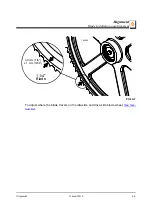
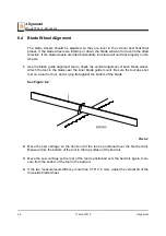
Page 107: ... 75 mm See Figure 6 6 Use the cant control adjustment to adjust the idle side blade wheel If the blade is too far forward on the wheel turn the cant control counterclockwise If it is too far back on the wheel turn the cant control clockwise 10 Check the position of the blade on the drive side blade wheel The blade should be posi tioned on the wheel as described for the idle side blade wheel Adjust...

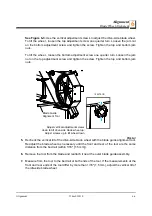
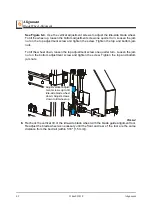
Page 108: ...uar ter turn Loosen the jam nut on the left adjustment screw and tighten the screw Tighten the left and right jam nuts To move the blade out on the wheel loosen the left adjustment screw one quarter turn Loosen the jam nut on the right adjustment screw and tighten the screw to Tighten the left and right jam nuts FIG 6 7 150075 3B Adjust horizontal adjustment screws left to move blade out on wheel ...

Page 109: ...Figure 6 8 2 Use the inside top and bottom screws to adjust the arm up until the slide pad touches the saw head brace tube Tighten the jam nuts 3 Adjust the blade guide arm in all the way toward the other blade guide 4 Use the outside top and bottom screws to adjust the arm up until the slide pad touches the saw head brace tube Tighten the jam nuts NOTE When adjusting the blade guide arm screws be...

Page 110: ...nt inside screw and the rear outside screw Turn the screws counterclockwise one full turn and tighten the jam nuts Loosen the jam nuts on the front outside screw and the rear inside screw Turn the screws clockwise until they touch the arm back off 1 4 turn and tighten the jam nuts 4 To move the blade guide end of the arm toward the rear of the sawmill loosen jam nuts on the front outside screw and...

Page 111: ...embly is referred to as the inner blade guide assembly The other blade guide assembly is mounted on the idle side of the saw head It is referred to as the outer assembly and is adjustable for various widths of materials to be pro cessed Blade guide alignment includes four steps Blade Deflection Blade Guide Vertical Tilt Blade Guide Flange Spacing Blade Guide Horizontal Tilt Perform the blade guide...

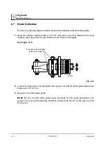
Page 112: ...th a tape from the top of the rail to the bottom of the blade See Figure 6 10 2 Loosen the bottom jam nut and tighten the top jam nut until the blade guide deflects the blade down 1 4 6 mm 3 Repeat for the other blade guide NOTE Be sure that the blade guard clears the blade on both guide assemblies The guard on the outer guide assembly should be checked with the arm all the way in and all the way ...

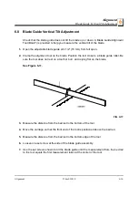
Page 113: ...tool close to a blade guide roller Be sure the tool does not rest on a tooth or burr and is lying flat on the blade See Figure 6 11 3 Measure the distance from the bed rail to the bottom of the tool 4 Move the carriage so that the front end of the tool is positioned above the bed rail 5 Measure the distance from the bed rail to the bottom edge of the tool 6 Loosen one set screw at the side of the ...

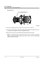
Page 114: ...il the measurement from the bed rail to the tool equals the other two measurements taken 10 Move the tool close to the other blade guide and repeat the previous steps NOTE If major adjustments to blade guide tilt were made remeasure the distance between the blade and the bed rails to ensure the correct 1 4 6 5 mm blade guide deflection Adjust if necessary FIG 6 12 SM0070 Loosen jam nuts and turn s...

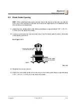
Page 115: ...e inner blade guide so the blade guide flange is approximately 1 16 1 8 1 5 3 0 mm from the back of the blade 2 Loosen one side and one top set screw shown Tap the blade guide forward or backward until properly positioned See Figure 6 13 3 Retighten the two set screws 4 Adjust the outer blade guide in the same way so the blade guide flange is approximately 1 16 1 8 1 5 3 0 mm from the back of the ...

Page 116: ...tween the back edge of the blade and the ruler at the end closest to the inner blade guide B 4 Measure between the back edge of the blade and the other end of the ruler A 5 The roller should be parallel to the blade A B or tilted slightly to the left A B 1 4 6 mm 6 Use the side set screws to adjust the horizontal tilt of the roller 7 Repeat Steps 3 7 for the inner blade guide roller NOTE Once the ...

Page 117: ...s See Figure 6 15 2 Swing a side support up so that it is vertical 3 Pull back at the top of the support to eliminate slack as if a log were being clamped against it 4 Check the angle of each support with a square on the board 5 The side support should be 90 to the bed rails Turn the adjustment bolt counterclock wise to tilt the top of the side support forward 6 Repeat for the remaining side suppo...

Page 118: ...bove one of the bed rails Mea sure from the bottom edge on a down set tooth of the blade to the top of the bed rail or stainless steel sleeve if applicable See Figure 6 16 2 Loosen the indicator bracket mounting bolts and adjust the bracket until the indicator is aligned with the correct mark on the scale Retighten the bracket mounting nut For example if the measurement from blade to bed rail was ...

Reviews: