Component Access & Removal
4-5
RANGES &
& R
RANGETOPS
Infrared Charbroiler Components:
Infrared Charbroiler Cover, Cover Spacer, Grate,
Screen, Blank-off Plate & Charbroiler Frame
Removal
• Lift the Charbroiler cover from the broiler frame.
• Lift the Charbroiler cover spacer from the broiler
frame.
• Lift the Charbroiler grille from the broiler frame.
• Lift the Charbroiler screen from the burner box.
• Lift the Charbroiler blank-off from the burner box.
• Lift the Charbroiler frame from the top of the unit.
(See Figure 3-8)
Infrared Charbroiler Orifice Removal
The orifice is located in the brass orifice elbow, which is
threaded into the orifice holder at the front of the burner
box.
NOTE:
It is possible to access and remove the orifice
without lifting out the infrared burner box, however lifting
the box out first will make the task easier.
To remove the orifice, first remove the heat shield and
disconnect the gas line from the brass orifice elbow.
Then, unscrew the elbow from the orifice holder, and
extract the orifice from the elbow with wrenches. (See
Figure 3-9)
Infrared Charbroiler Burner Box Removal
After removing the components listed above, extract the
screw securing the sparker bracket. Then, extract the
screw from the rear of the IR burner box. Extract the
screws from the heat shield/baffle and lift it out.
Disconnect the gas line from the brass orifice elbow
and lift the burner box out. (See Figure 3-10)
Infrared Charbroiler Sparker Removal
The infrared Charbroiler sparker is attached to a brack-
et with a screw and then mounted 1/32” above the sur-
face of the burner tile. The sparker wire is then insert-
ed into a wire sleeve and routed to the spark module
which is located on the back side of the unit.
In order to remove the Charbroiler sparker, the unit
must be pulled from its installation and the back panel
must be removed.
Once the back panel is removed, disconnect the spark-
er wire from the module. Extract the mounting screw
from the sparker bracket and pull the sparker wire up
through oblong hole in the back wall. (See Figure 3-10
& 3-16)
Cover Spacer
Cover
Grille
Screen
Charbroiler Frame
Blank-off Plate
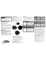
Figure 3-8. Components that Lift Off
Figure 3-10. IR Charbroiler Burner & Sparker
Figure 3-9. IR Charbroiler Orifice Removal
IR Charbroiler Orifice
Orifice Elbow
Sparker
Burner Box
Heat Shield
Gas Line
Summary of Contents for RT362F
Page 2: ......
Page 3: ...General Information RANGES R RANGETOPS 1 1 SECTION 1 GENERAL INFORMATION ...
Page 13: ...Theory of Operation 2 1 RANGES R RANGETOPS SECTION 2 THEORY OF OPERATION ...
Page 20: ...RANGES R RANGETOPS Theory of Operation 2 8 ...
Page 21: ...Installation Information RANGES R RANGETOPS 3 1 SECTION 3 INSTALLATION INFORMATION ...
Page 26: ...RANGES R RANGETOPS Installation Information 3 6 ...
Page 27: ...Component Access Removal 4 1 RANGES R RANGETOPS SECTION 4 COMPONENT ACCESS AND REMOVAL ...
Page 43: ...Troubleshooting Guide 5 1 RANGES R RANGETOPS SECTION 5 TROUBLESHOOTING GUIDE ...
Page 53: ...Technical Data 6 1 RANGES R RANGETOPS SECTION 6 TECHNICAL DATA ...
Page 56: ...RANGES R RANGETOPS Technical Data 6 4 ...
Page 57: ...R RA AN NG GE ES S R RA AN NG GE ET TO OP PS S Wiring Diagrams 7 1 WIRING DIAGRAMS SECTIO N 7 ...
Page 88: ...R RA AN NG GE ES S R RA AN NG GE ET TO OP PS S 7 32 Wiring Diagrams ...


