


© 2006 Wohler Technologies Inc. ALL rights reserved
18
AMP-S8
User Manual P/N
821640
Rev-
B
7c
7b
7a
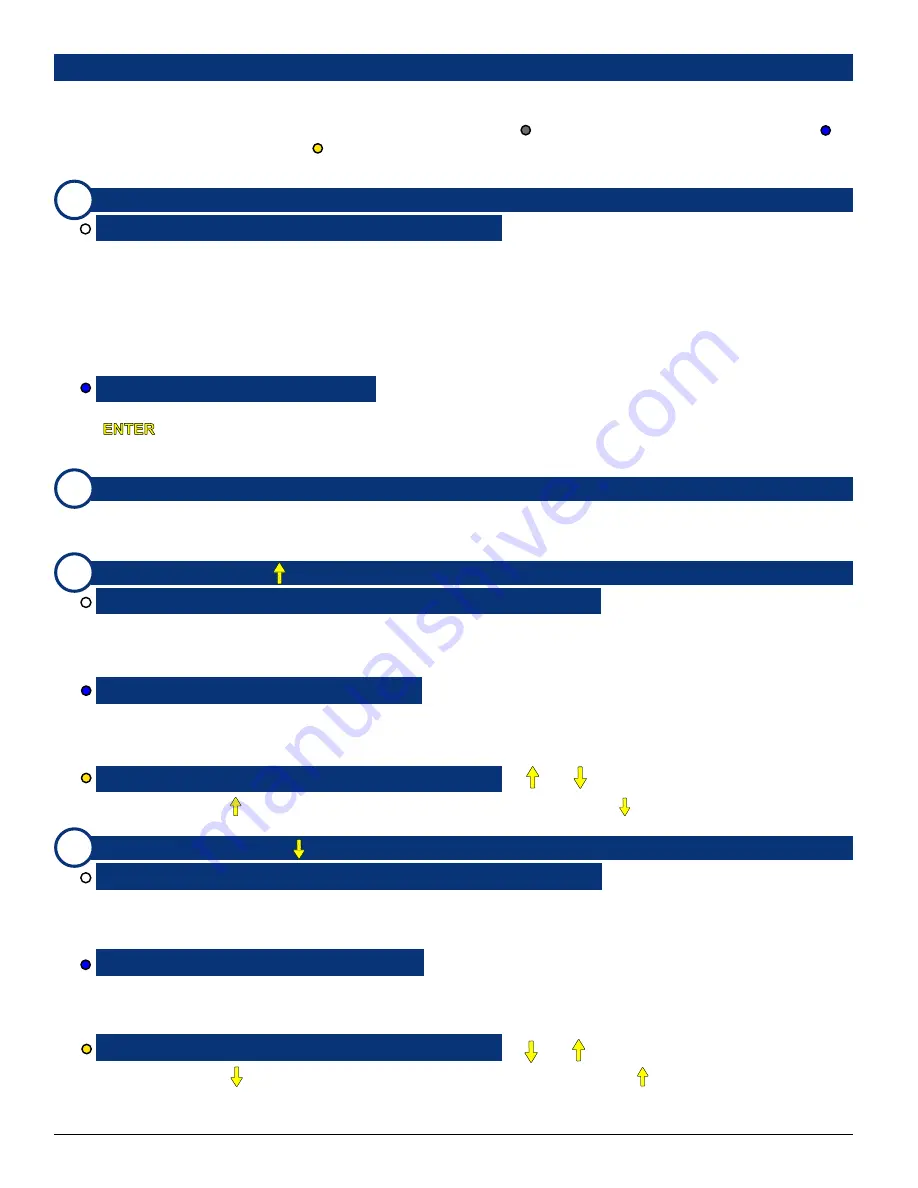
User Interface Features
Please refer to
Figure-2d
on page
17
to familiarize yourself with the front panel user interface controls of the
AMP-S8
units. The
following sections describe these features and are referenced, by number/letter, to
Figure-2d
. For multi-function controls, a color-coded
dot identifies the mode in which a particular function operates; GRAY dot ( ) =
Normal Operational Mode
, BLUE dot ( ) =
FUNCTION (
FN
) Modes
, YELLOW dot ( ) =
Setup Mode
). The user should refer to the
User Interface Function Guide
starting on
page
23
where operation is described in greater detail and contents are referenced by
function
rather than
feature
.
CHANNEL MIX 1-8 (
PRESETS 1-4
) Buttons
Configuring a CHANNEL MIX for Monitoring:
> CHANNEL MIX Button 1-8
The mixing (summing) feature is activated whenever any
CHANNEL MIX Button
is pressed, and is indicated by the
selection display showing
MIX
in the upper right and left of the display.
Each repeated press of a
Channel Mix Button
sequencially assigns that channel to the left, both, right, or neither speaker
channel. With each successive button press, the color of the associated
CHANNEL MIX LED
(
Item 7b
), and the mixing/
routing of that channel, cycles through the following sequence:
1)
GREEN (to
left
speaker only),
2)
GREEN/AMBER
alternating (to both
left
and
right
speakers),
3)
AMBER (to
right
speaker only),
4)
OFF (
not
mixed or routed into either
speaker).
Recalling and Saving Presets:
>
FN Button
+
PRESETS Button 1-4
Press and hold the
FN Button
and then press the corresponding
PRESETS Button (1-4)
. At the prompt, press the
NTER
Button
to accept the preset. See the
Save Preset
section on page
29
for how to save the current configuration as
a preset. See pages
28-30
for more information about creating, naming, recalling, and erasing input presets within
Setup
Mode
.
CHANNEL MIX LEDs 1-8
These LEDs are used to indicate the speaker mix of channels as selected when using the
CHANNEL MIX Buttons
(
Item
7a
). See
CHANNEL MIX Selection
section on page
25
or
Item 7a
above for a description of the function of these
indication LEDs.
L UP (
SINGLE
or ) Button
Selection Navigation Using the UP and DOWN Buttons:
> L UP (or L DOWN) Button
The
L UP
and
L DOWN
(and
R UP
and
R DOWN
)
Buttons
are used to cycle through and select different channels or
channel combinations, depending on which
Selection Mode
is selected. See
Single Channel Selection
,
Paired Channel
Selection
, and
Downmix Selection
on page
25
for more information about using these buttons for channel selection.
Making Single Channel Selections:
>
FN Button
+
SINGLE Button
Single Channel Select Mode
is enabled by pressing and holding the
FN Button
(
Item 7j
)and then pressing the
SINGLE
Button
. Press the
L UP
or
L DOWN Buttons
to cycle up or down through each channel selection for the
left
speaker;
press the
R UP
or
R DOWN Buttons
to cycle up or down through each channel selection for the
right
speaker.
Cycling Through Selections in Setup Mode:
> (or ) Button
In
Setup Mode
, the
Button
is used to cycle
upward
through selections, and the
Button
is used to cycle
downward
.
Also see
Enabling Setup Mode
(page
28
) and the
Setup Menu Navigation Flow Chart
(
Figure-2e
, page
31
).
L DOWN (
PAIRS
or
) Button
Selection Navigation Using the UP and DOWN Buttons:
> L DOWN (or L UP) Button
The
L UP
and
L DOWN
(or
R UP
and
R DOWN
)
Buttons
are used to cycle through and select different channels or
channel combinations, depending on which
Selection Mode
is selected. See
Single Channel Selection
,
Paired Channel
Selection
, and
Downmix Selection
on page
25
for more information about using these buttons for channel selection.
Making Paired Channel Selections:
>
FN Button
+
PAIRS Button
Paired Channel Select Mode
is enabled by pressing and holding the
FN Button
and then pressing the
PAIRS Button
.
After entering this mode, the
L UP
and
L DOWN Buttons
or
R UP
and
R DOWN Buttons
are used to cycle up or down
through channel
pair
selections
1/2
,
3/4
,
5/6
, or
7/8
each channel being assigned, respectively, to the left and right speakers.
Cycling Through Selections in Setup Mode:
> (or ) Button
In
Setup Mode
, the
Button
is used to cycle
downward
through selections, and the
Button
is used to cycle
upward
.
Also see
Enabling Setup Mode
(page
28
) and the
Setup Menu Navigation Flow Chart
(
Figure-2e
, page
31
).
Section 2:
Operation
7d


