GMG-K / GMG-L Operation manual
Page 1 of 58
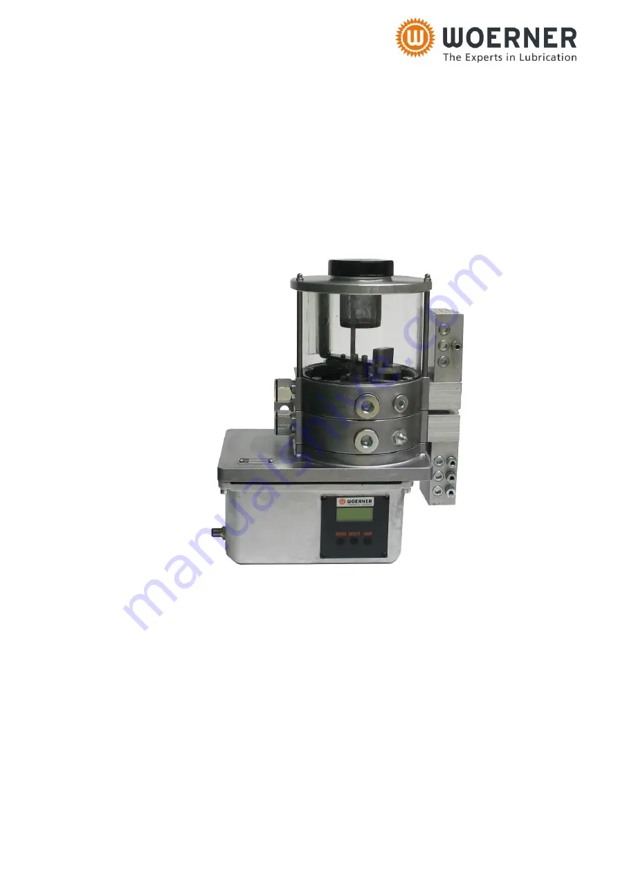
B0793 / B0796
PUMP UNIT
TYPE GMG-K / GMG-L
Translation of the
original operation manual
Version EN 06/2018
Page 1: ...GMG K GMG L Operation manual Page 1 of 58 B0793 B0796 PUMP UNIT TYPE GMG K GMG L Translation of the original operation manual Version EN 06 2018...
Page 2: ...nconsistency in the translated text occurs the original German operation manual should be referred to for clarification or the manufacturer contacted Copyright Unless permitted explicitly the dissemin...
Page 3: ...3 5 2 Dimensions 10 3 5 3 Base unit 11 3 5 4 Level monitoring option 12 3 5 5 Control 12 3 5 6 Progressive distributors option 13 3 5 7 Electric connection of the pump unit 13 3 5 8 Level monitoring c...
Page 4: ...ing 46 11 3 1 One row pump unit Time ON Time OFF variant 46 11 3 2 One row pump unit Time ON Distributor pulses OFF variant 47 11 3 3 One row pump unit Machine pulses ON Time OFF variant 48 11 3 4 One...
Page 5: ...are obliged to read and understand this operation manual and in particular its section Safety regulations It is your safety that is at stake Should you have any question or uncertainty contact WOERNER...
Page 6: ...ns and notes have the following meanings Danger Any danger threatening immediately and capable of causing serious personal injuries Warning Any possibly dangerous situation capable of causing serious...
Page 7: ...at the side of the pump body and contains information as follows Manufacturer Type e g GMG K No order number e g 612345 1 Model year 2 4 Manufacturer and contact address Eugen Woerner GmbH Co KG Hafen...
Page 8: ...esides the pump unit s area of application is determined by the medium to be delivered Hence when determining the area of application you also need to refer to the technical data sheets for the medium...
Page 9: ...onventional one may cause serious personal and property damage The delivery of gases liquefied gases gases dissolved under pressure vapours and liquids the vapour pressure of which exceeds at the perm...
Page 10: ...ns Dimensions excluding filler lid Weight With reservoir 1 and two pump element rows 6 0 kg without progressive distributors without lubricant Version 1 row with 3 pump elements Version 2 row with 6 p...
Page 11: ...r pump element 16 GMG K 0 16 cm per pump element 04 GMG L 0 04 cm per pump element 11 GMG L 0 11 cm Admissible delivery pressure 250 bar Temperature range 20 60 C GMG K with grease 0 60 C Motor connec...
Page 12: ...A Maximum switching power 1 5 W Temperature range 20 60 C Contact function PNP opener When connecting inductive or capacitive loads the relevant sup pressor circuits diode RC element varistor need to...
Page 13: ...chnical data is as follows Switching voltage 10 36 VUC Switching current max 25 mA Switching power max 0 9 VA Temperature range 5 60 C Outer material PA 1 4305 3 5 7 Electric connection of the pump un...
Page 14: ...r to release the pump in the Time mode the pin 2 is to be supplied with 24 V In Pulse mode the machine pulses have to be supplied to pin 2 Version without control Pin 1 24 VDC 0 VDC1 2 3 0 VDC 24 VDC1...
Page 15: ...nection socket 8 1 This is the connection for the monitoring of a progressive distributor in the lower pump element row Connection socket 8 2 This is the connection for the monitoring of a progressive...
Page 16: ...very function When the eccentric shaft 3 is rotating the delivery piston 2 1 of every pump element of the respectively delivering pump element row performs a suction and delivery stroke per rotation e...
Page 17: ...pump elements do not deliver The integrated control unit can be used to programme the operation and off duty times for the delivery with stirring and the stirring without delivery independently from e...
Page 18: ...6 cm delivery volume pump element is marked by a black ring R whereas the 0 04 cm delivery volume pump element is marked by a white ring R 4 5 2 GMG L Pump elements The pump elements of the GMG L unit...
Page 19: ...lable during pump switch on must be delayed by approx 5 seconds Lubricant available No lubricant available permanent signal intermittent signal Level control C Level control F Minimum level monitoring...
Page 20: ...ment is delivered to the outlets progressively For more information about the functioning of the distributors see data sheets P0378 and P0177 respectively Functional control In conjunction with the mo...
Page 21: ...2 Requirements on user training Any person getting to work on the pump unit must be authorised and trained for that purpose by the operator They must be able to recognise and avoid potential risks Thi...
Page 22: ...d measures prescribed there are no residual risks to persons and objects within the pump unit s area If the pump unit is delivered in pre filled condition the product and safety data sheets related to...
Page 23: ...an condition only It is prohibited to remove modify bridge or bypass any and all protection safety or monitoring facilities It is prohibited to reconstruct or modify the pump unit The operator should...
Page 24: ...scope of delivery may still contain residues of blue dyed test oil 6 3 Installation The pump unit is ready for wall mounting It is to be secured by means of two M10 screws The mounting surface must be...
Page 25: ...oring devices with the connecting cables to the pump unit see sub section 3 5 9 Connect the pump unit to the voltage supply see sub section 3 5 7 Ground the pump unit through the potential connection...
Page 26: ...selecting the transmission oil however proper compatibility with the lubricant used needs to be ensured b Bleeding the pump unit Bleeding at the pump element If no progressive distributor is attached...
Page 27: ...tributors with the lube lines These lines must be clean and free of any obstruction You may not connect the lube lines to the lube points unless the lubricant comes out free of air Check all connectio...
Page 28: ...peration external release 24 V on Pin 2 On the control you can adjust various menu items and parameters The meanings of the various menu items are as follows CODE Menu release P1 Selection between tim...
Page 29: ...nd upper element row separately In case of switch on parameter overlapping during operation the delivery by the running row of elements will be stopped first Then the other row of elements starts deli...
Page 30: ...four or eight different control variants and two special functions 7 1 2 Changing the password How to change a password 1 Switch off voltage supply 2 Press MODE SELECT SAVE 3 Keep keys depressed and...
Page 31: ...e distributor pulses has released a specified number of pulses The distributor monitoring P7 will be switched on in this mode automatically when P5 is set to 1 P7 will not be reset automatically When...
Page 32: ...articular number of pulses from the monitored progressive distributor Here the cycle time means the time that elapses between the beginning of a delivery interval and the beginning of the next one For...
Page 33: ...that elapses between the beginning of a delivery interval and the beginning of the next one For both the lower and upper row of elements different cycle times as well as progressive distributor pulses...
Page 34: ...reset automatically When changing the mode or resetting P15 to 0 the status of P17 needs to checked and reset manually if necessary Machine pulses ON Lower row distributor pulses OFF Upper row time O...
Page 35: ...st Then switch over to the other row will be made The P7 and P17 distributor monitoring will be switched on this mode automatically when P5 and P15 are set to 1 P7 and P17 will not be reset automatica...
Page 36: ...r a while in the ON mode of operation Test By means of the Test function you can initiate a test run of the pump unit When the keys SAVE and MODE are pressed in this order quickly one after the other...
Page 37: ...too high 5 No lubricant delivery Drive motor not running Check electric connenctions Check electric voltage at the motor Check the fuse Check the motor Reservoir is empty Refill lubricant Air included...
Page 38: ...the unit with oil refill is to be made into the reservoir directly For operation with grease it is recommended to refill through the filler connection by using a filling pump as such method ensures a...
Page 39: ...lectricians in accordance with DIN VDE 1000 10 8 1 Cleaning Important The pump unit must not be cleaned by means of high pressure cleaners or compressed air Important The use of solvent containing cle...
Page 40: ...of the pump unit Weekly 8 4 Repair Changing the pump element Note Prior to pump element removal the reservoir must be emptied since otherwise lubricant may spill Note When removing the pump element be...
Page 41: ...essories Pressure control valves To limit the maximum operating pressure pressure control valves 10 can be connected to the pump element 2 or instead of the bleeding screw to the progressive distribut...
Page 42: ...ent of compliance form for all products that are to be returned to us Without submission of the fully completed form no return shipment can be accepted and processed To ensure speedy handling you are...
Page 43: ...y discharged and cleaned 2 the residual contaminations left are free of any substance being harmful to health or environment 3 the materials used by us in the product s comply with the notes on the pu...
Page 44: ...he declaration of conformity We hereby declare that the product Pump unit type GMG K GMG L as of model year 2018 meets all relevant provisions of the directive on machinery 2006 42 EC Furthermore the...
Page 45: ...GMG K GMG L Operation manual Page 45 of 58 B0793 B0796 11 2 Declaration of conformity...
Page 46: ...ON Time OFF variant MODE SELECT MODE SELECT MODE SAVE SELECT MODE SELECT SELECT SAVE MODE SELECT SELECT SAVE MODE SELECT SELECT SAVE MODE SELECT SELECT SAVE MODE SELECT MODE SELECT SAVE MODE SELECT S...
Page 47: ...e row pump unit Time ON Distributor pulses OFF variant MODE SELECT MODE SELECT MODE SAVE SELECT MODE SELECT SELECT SAVE MODE SELECT SELECT SAVE MODE SELECT SELECT SAVE MODE SELECT SELECT SAVE MODE SEL...
Page 48: ...ON Time OFF variant MODE SELECT MODE SELECT MODE SAVE SELECT MODE SELECT SELECT SAVE MODE SELECT SELECT SAVE MODE SELECT SELECT SAVE MODE SELECT MODE SELECT SAVE MODE SELECT SELECT SAVE MODE SELECT M...
Page 49: ...3 4 One row pump unit Machine pulses ON Distributor pulses OFF variant MODE SELECT MODE SELECT MODE SAVE SELECT MODE SELECT SELECT SAVE MODE SELECT SELECT SAVE MODE SELECT SELECT SAVE MODE SELECT SEL...
Page 50: ...LECT SAVE MODE SELECT SELECT SAVE MODE SELECT SELECT SAVE MODE SELECT SELECT SAVE MODE SELECT MODE SELECT SAVE MODE SELECT SELECT SAVE MODE SELECT SELECT SAVE MODE SELECT SELECT SAVE MODE SELECT SELEC...
Page 51: ...SELECT MODE SELECT MODE SAVE SELECT MODE SELECT SELECT SAVE MODE SELECT SELECT SAVE MODE SELECT SELECT SAVE MODE SELECT SELECT SAVE MODE SELECT MODE SELECT SAVE MODE SELECT SELECT SAVE MODE SELECT SE...
Page 52: ...SELECT MODE SELECT MODE SAVE SELECT MODE SELECT SELECT SAVE MODE SELECT SELECT SAVE MODE SELECT SELECT SAVE MODE SELECT SELECT SAVE MODE SELECT SELECT SAVE MODE SELECT SELECT SAVE MODE SELECT SELECT...
Page 53: ...s OFF Upper row distributor pulses OFF variant MODE SELECT MODE SELECT MODE SAVE SELECT MODE SELECT SELECT SAVE MODE SELECT SELECT SAVE MODE SELECT SELECT SAVE MODE SELECT SELECT SAVE MODE SELECT SELE...
Page 54: ...CT MODE SELECT SELECT SAVE MODE SELECT SELECT SAVE MODE SELECT SELECT SAVE MODE SELECT MODE SELECT SAVE MODE SELECT SELECT SAVE MODE SELECT SELECT SAVE MODE SELECT SELECT SAVE MODE SELECT SELECT SAVE...
Page 55: ...OFF variant MODE SELECT MODE SELECT MODE SAVE SELECT MODE SELECT SELECT SAVE MODE SELECT SELECT SAVE MODE SELECT SELECT SAVE MODE SELECT MODE SELECT SAVE MODE SELECT SELECT SAVE MODE SELECT SELECT SA...
Page 56: ...OFF variant MODE SELECT MODE SELECT MODE SAVE SELECT MODE SELECT SELECT SAVE MODE SELECT SELECT SAVE MODE SELECT SELECT SAVE MODE SELECT SELECT SAVE MODE SELECT SELECT SAVE MODE SELECT SELECT SAVE MO...
Page 57: ...distributor pulses OFF Upper row distributor pulses OFF variant MODE SELECT MODE SELECT MODE SAVE SELECT MODE SELECT SELECT SAVE MODE SELECT SELECT SAVE MODE SELECT SELECT SAVE MODE SELECT SELECT SAVE...
Page 58: ...0 P8 Delivery time setting in hours lower row of elements 0 100 0 P9 Delivery time setting in minutes lower row of elements 0 59 1 P10 Selection of stirring function lower row of elements Yes 001 No...