Project planning guide
cyber
®
reaction wheel 2
en-38
Doc. no.: 5022-D060586
Revision: 02
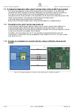
The mounting bores for the reaction wheel are at GND potential for the cyber
®
reaction wheel
starter kit as well as the 4 mounting bores at the corners. For integration into the satellites, the
mounting bores for the reaction wheel and the entire housing of the reaction wheel can be on
GND and chassis potential. This allows power to be supplied by a grounded or ground-free
voltage source. The voltage difference between chassis and GND must not exceed 30 V.
•
Notice: Alternatively, the housing of the cyber
®
reaction wheel could be mounted isolated
(connected neither to GND nor to chassis). However, we recommend connecting the
mounting bores with a high resistance of 100 kΩ to 1 MΩ to GND to compensate for possible
charges between GND and the housing to prevent the permitted 30 V from being exceeded.
4.2 Mechanical integration of the cyber
®
reaction wheel 2
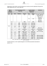
The through holes for the M2 fastening screws must have a diameter of 2.6 mm. A position
tolerance of 0.2 mm for compensation of any position and length deviations of the connectors
must be observed.
4.3 Installation of the cyber
®
reaction wheel 2
•
Observe the safety and processing instructions for the threadlocker
to be used.
•
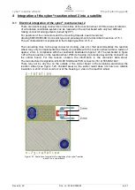
Connect the connector of the mounting
position used with the PCB connector
on your attachment part. While doing
so, make sure that the connector is
engaged properly and not damaged.
•
Coat the fastening screws with a
threadlocker.
•
Fasten the drive system with the
fastening screws through the threaded
bores (A or B). When tightening,
ensure that the connector is not
subject to any lateral loads.
•
Use screws with property class A2-70 or titanium grade 5 and tighten them with a maximum
torque of 0.11 Nm. Also observe the load capacity of the screw head.
•
Use the maximum screw-in depth.
•
Attach the drive system so that the name plate can still be read.
•
Make sure that the unused second connector is protected against contact with conductive
components.
Fastening screws that are screwed in too far can damage the
drive system.
•
Screw in the screws only up to their maximum depth.
see dimensional drawing (5007-D060499).
NOTICE


