background image

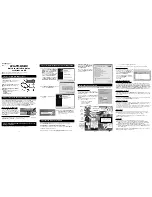
CONNECTIONS AND INDICATIONS

5

3.  CONNECTIONS AND INDICATIONS

1

2

3

5

4

7

8

9

10

6

1.  Antenna inputs 1:1 and 2:1

Connect the satellite/terrestrial/cable signal for Ch1 and Ch2 
or for all three output channels here.

2.  Antenna input 1:2 and 2:2

Connect the satellite/terrestrial signal for Ch3 here (Source 
duplication mode OFF).

3.  Common Interface 1:1

Insert a Common Interface module into this slot (Supports 
decryption for Channel 1 and 2)

4.  Common Interface 1:2

Insert a Common Interface module into this slot (Supports 
decryption for Channel 3)

5.  Common Interface 2:1

Insert a Common Interface module into this slot (Supports 
decryption for Channel 4 and 5)

6.  Common Interface 2:2

Insert a Common Interface module into this slot (Supports 
decryption for Channel 6)

7.  Ethernet port 1:1

8.  Ethernet port 2:1

RJ-45 port for 10/100 baseT Ethernet. Connect your PC to 
these ports for management, IP input and upgrades.

9.  RF-output(s) 1:1-3 and 2:4-6

Combined 3 channel RF outputs for connection to your 
SMATV network

10.  Indicator LED(s)

Status indicator

Summary of Contents for MICRON MyM Pro

Page 1: ...MyM Pro MICRON Installation Guide www wisi se...

Page 2: ...8 5 1 Overview menu 8 5 2 Input settings 9 5 2 1 DVB T T2 reception 9 5 2 2 DVB S S2 reception 10 5 2 3 DVB C reception 10 5 2 4 IPTV reception 11 5 3 Output settings 12 5 3 1 Modulation 12 5 3 2 Dec...

Page 3: ...N has a multifunctional tuner that receives DVB S S2 DVB T T2 DVB C and IP transmissions The MyM Pro MICRON unit is delivered with hardware and software that supports MPEG 2 MPEG 4 decoding HD downsca...

Page 4: ...owing items are included in the package Every unit is quality controlled by us before delivery Should any items be missing when unpacking please contact our support service see page 3 for contact info...

Page 5: ...Channel 1 and 2 4 Common Interface 1 2 Insert a Common Interface module into this slot Supports decryption for Channel 3 5 Common Interface 2 1 Insert a Common Interface module into this slot Support...

Page 6: ...you set a static IP address on your computer For example set your PC to IP address 192 168 0 19 and Net mask 255 255 255 0 4 1 TCP IP SETTINGS FOR WINDOWS XP Select Start Control panel and Network co...

Page 7: ...er and write the IP address 192 168 0 20 and 192 168 0 21 for second port in the address field of your browser 4 3 SETTINGS OF IP ADDRESS Click the System options menu and then press Networking to set...

Page 8: ...ners are locked to a signal firmware version bootloader version hardware revision serial number and current IP Network settings A Name and Description can be written by click on the Edit button INSTAL...

Page 9: ...st for RF output Ch3 The tuner can also be Disabled Bandwidth can be selected between 6 7 or 8 MHz Select input channel from Channel name scroll list or write the center frequency of the wanted Mux an...

Page 10: ...is Orange or Red the input level is out of recommended window too low or too high If you have an MyM Pro MICRON 6 proceed with next two tuners Tuner 3 and Tuner 4 after moving the TP cable to the othe...

Page 11: ...cable to the other RJ 45 port if not using switch Tuner 3 provides the service list for RF output 4 and 5 Tuner 4 provides the service list for RF output 6 5 2 4 IPTV RECEPTION For receiving from IPT...

Page 12: ...ls by using Channel name scroll list or write the frequency Modulator enabled can be set to OFF to switch off the RF out There is receiving information of Running status ONID TSID and SID for each Mod...

Page 13: ...S CONFIGURATION Setting for this is depending on what settings connected TV set s have Setting of WSS is also depending on setting of Video conversion AUDIO LANGUAGE Select which language to receive a...

Page 14: ...in the received PMT If there is no subtitling only None will be present Subtitle configuration have the different choice None Auto In picture and Out of picture 5 3 3 DECODER STATUS Shows status of Vi...

Page 15: ...ges colour to green Also the Name of the service will come green when decoding is running for both Audio and Video The service list gives following information Green colour indication Shows type of se...

Page 16: ...need for changing that After a change is made the Save button must be clicked If changes are made and does not work you can get the default settings again by a click on the Restore defaults button an...

Page 17: ...case you have forgotten your IP address please consult the WISI support web site and download free of charge our tool IP supporter can be downloaded from www wisi se This tool finds all MyM Pro MICRO...

Page 18: ...n in the MyM Pro MICRON by click on Backup that can be useful if unit has to be swapped or if multiple installations are made with the same settings Use Browse and Restore for upload of a saved backup...

Page 19: ...that all other connections have been made A coaxial cable of good quality with an F connector should be connected to the Antenna input and another one from the RF output to the SMATV network Make all...

Page 20: ...ces Available modes as described adjacently Multi Standard Tuners MyM Pro MICRON 3 2 individually selectable tuners 2 Type F female 75 connectors MyM Pro MICRON 6 4 individually selectable tuners 4 Ty...

Page 21: ...DECLARATION OF CONFORMITY 21 8 DECLARATION OF CONFORMITY The document for Declaration of Conformity is available for download from www wisi se Further information at www wisi se...

Page 22: ...net Protocol network Connector for a PCMCIA module used for decrypting encrypted TV programs CAM Modules should comply with the DVB CI standard Standard definition TV 576i in Europe Service Management...

Page 23: ......

Page 24: ...si se WISI Norden AB Teknikringen 1B 583 30 Link ping SWEDEN Phone 46 13 21 09 00 E mail info wisi se Web www wisi se Technical modifications reserved WISI cannot be held liable for any printing error...

Reviews: