25
INSTALLATION MANUAL
AIR HEATER TYPE DXC
12 Exploded view and spare parts
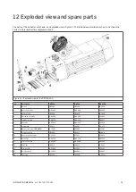
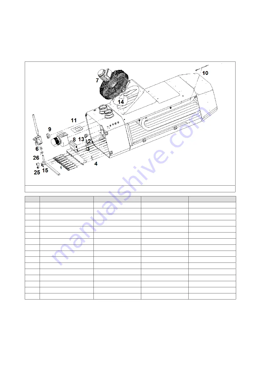
The parts of the air heater are shown in an exploded view in figure 22. The table below describes each part and shows the
correct article number for a replacement part.
Figure 22 - Exploded view of the DXC60-100
No.
Description
DXC60
DXC80
DXC100
1
Burner
IB3204
IB3204
IB3204
2
Ignition electrode
GA3400
GA3400
GA3400
3
Ignition cable
IB3929
IB3929
IB3929
4
Ionisation electrode
GA3402
GA3402
GA3402
5
Combustion fan
GA4516
GA4516
GA4517
6
Gas valve
GA3314
GA3314
GA3314
7
System fan
IP4811
IP4801
IP4813
8
Burner control unit (EBM966)
GY5901
GY5901
GY5901
9
Pressure switch
IB3904
IB3911 IB3904
10
Heat exchange sensor
GY3935
GY3935
GY3935
11
Gasket set
GA6716
GA6716
GA6716
13
Selection switch
GD5284
GD5284
GD5284
14
Fan blade
IK4212
IK4214
IK4223
15
Display PCB
GY5902
GY5902
GY5902
25
Rectifier block
GY3921
GY3921
GY3921
26
Fan relay
IK5200
IK5200
IK5200

