9
INSTALLATION MANUAL
AIR HEATER TYPE DXC
NOTICE
All gas supply lines must be mounted without any
mechanical tension.
NOTICE
Always clean the inside of a gas supply line
before connecting it to the air heater. Place a gas filter in
the supply line when needed.
CAUTION!
When using pressures above 60 mbar to test
the supply lines, always close the manual isolation valve of
the air heater.
For United Kingdom only:
The supply line for gas must comply with the Gas
Engineers publications UP-1 and UP-2, as well as with BS
6891.
4.4 Electrical connection
The electrical installation must comply with local and
national requirements as well as IEE regulations.
4.4.1
Power supply
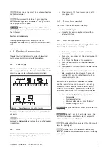
The air heater requires an earthed power supply of 230 V/
AC. A supply of 400 V/AC + Neutral is optional. The control
circuit is a two wire low voltage bus communication.
L
N
230 Vac
PE N
L
L
N
PE
11 12
13 14 PE
N
L
M1
4
5
6
7
PE
RT
Bus com
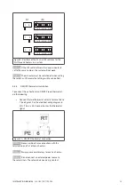
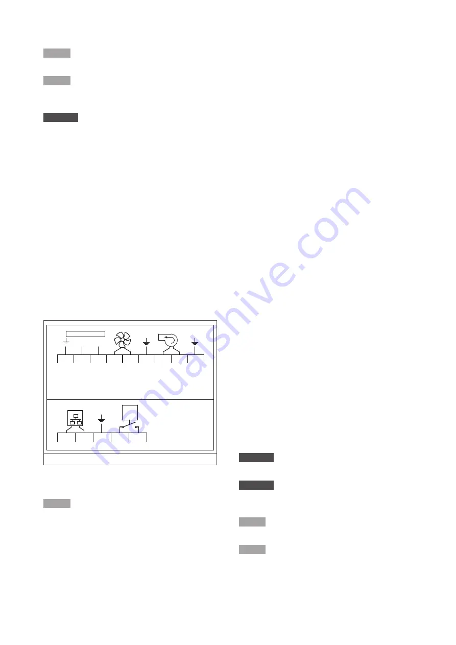
Figure 4 - The air heater's connection clamps
A supply cord with a connection plug is supplied with the
air heater.
NOTICE
Make sure you do not damage the supply cord. A
damaged cable needs to be replaced by a qualified person
immediately.
4.4.2
Fuse
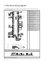
One fuse is present on the air heater’s control board (see
the electrical wiring diagram in §11).
• When replacing this fuse, always use one of the
same type (5AT).
4.5 Room thermostat
The air heater can be controlled in two ways:
• by an ON/OFF signal;
• through a bus communication system with an
external interface.
4.5.1
Installation requirements
Following these requirements when placing the thermostat
to ensure the heater functions correctly:
• Make sure that air can circulate around the
thermostat.
• Make sure the sun does not shine directly upon the
thermostat.
• Do not place the thermostat on a cold wall.
• Place the thermostat on an inner wall free from
draught.
• Never place the thermostat within the throw of the
heater.
• Never mount the thermostat near the aerials of
internal communication networks. These emit
radiation that can disturb the thermostat. Keep
several meters distance.
In all cases, the communication between the heater
and the thermostat is based on a two wire, low-voltage
connection. (see the electrical wiring diagram in §11).
Follow these instructions to prevent malfunction of the
installation and damage to the thermostat or air heater:
• Use a cable with the following specifications:
–
Signal cable.
–
Shielded and twisted.
–
Minimum dimensions: 1 x 2 x Ø0,8 mm
2
.
–
Maximum length: 200 m.
CAUTION!
Keep the thermostat cable separated from the
mains cables.
CAUTION!
Connect the cable’s earth shield only to the
earth terminal inside the air heater. Do not connect the
other end of the cable’s earth shield.
NOTICE
A cable with a thickness of less than 0.8 mm will
result in a poor signal.
NOTICE
A cable that is not shielded and twisted may
result in a disturbed communication in an EMC-unfriendly
environment.


