background image

FM08 Product Reference Guide


66 


Connecting to 4G Network 

Perform the following to connect to your 4G network: 

1. 

Verify that WWAN Mode is enabled (this icon will turn into Orange color), this verifies that your WWAN radio 

module is enabled 

2. 

Open the Skylight application (tap Start > All programs > Sierra Wireless > Skylight) or (tap Start > Desktop > 

Skylight) 

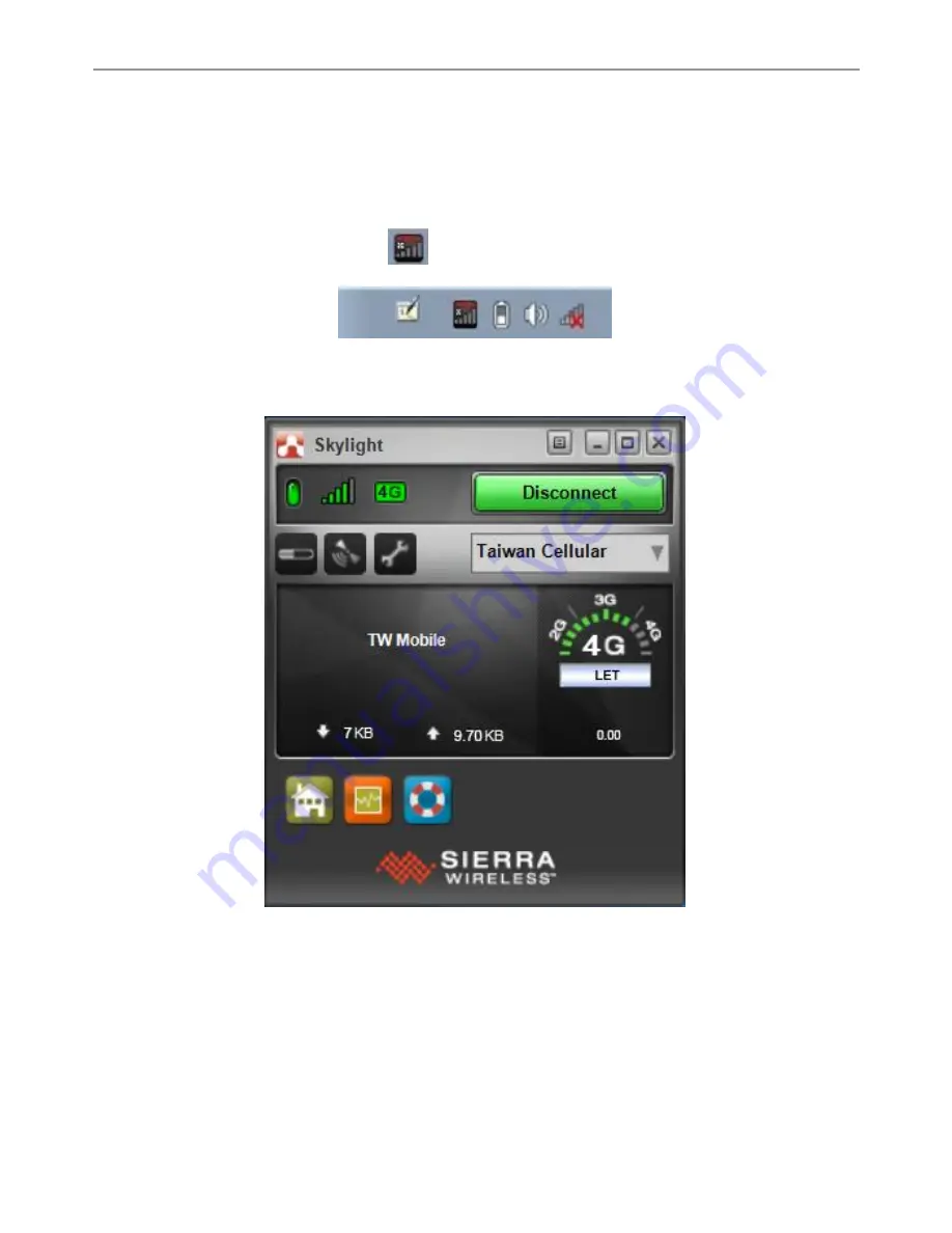
The skylight application window opens and the 


icon appears in the Windows notification area as following 

picture. 


3. 

The application detects the SIM card and display network information on the Skylight main screen 

4. 

Tap connect to connect the 4G network, once connected the Skylight main screen displays the network 

connection information, such as signal strength, connection speed and bitrate transfer 


Summary of Contents for FM08

Page 1: ... Vehicle Mounted Computer Microsoft Windows 7 Professional for Embedded System Product Reference Guide Version III For more information on this and other Winmate products please visit our website at www winmate com ...

Page 2: ...ches away from the human body Disclaimer Winmate Inc reserves the right to make any product changes without notice including circuits and or software described or contained in this manual in order to improve design and or performance Winmate Inc assumes no responsibility or liability for the use of the described product s conveys no license or title under any patent copyright or masks work rights ...

Page 3: ...e limits for a Class B digital device pursuant to Part 15 of the FCC Rules These limits are designed to provide reasonable protection against harmful interference in residential installation This equipment generates uses and can radiate radio frequency energy and if not installed and used in accordance with the instructions may cause harmful interference to radio communications However there is no...

Page 4: ...quipment complies with FCC RF radiation exposure limits set forth for an uncontrolled environment This device was tested for operations with the device contacted directly to the human body to the back side of the EUT To maintain compliance with FCC RF exposure compliance requirements avoid direct contact to the transmitted antenna during transmitting IC Regulations Le présent appareil est conforme...

Page 5: ...mply with the e i r p limit and The maximum antenna gain permitted for devices in the band 5725 5850 MHz to comply with the e i r p limits specified for point to point and non point to point operation as appropriate as stated in section A9 2 3 In addition High power radars are allocated as primary users meaning they have priority of the band 5250 5350 MHz and this radar could cause interference an...

Page 6: ...ional 14 POWER MANAGEMENT MODE 15 Full ON Mode 15 Standby and Sleep Mode 15 Hibernate Mode 15 OFF Mode 16 Ignition Control 16 POWER CONTROL 17 Power Switch 17 Power Button 17 BATTERY 18 UPS Battery 18 Backup Battery 19 EXTERNAL CONNECTORS 20 Connector Pinouts 20 ANTENNA CONNECTIONS 25 Internal Wi Fi Antenna 25 External Vehicle Remote Antenna 25 KEYBOARD OPTIONS 27 66 Key QWERTY Keyboard 27 USB Key...

Page 7: ...63 Connecting to 4G Network 66 USING CAMERA FEATURES 67 Opening the Camera 67 The Camera Screen 67 Shooting Photos 68 Recording Videos 68 Camera Settings 69 USING RECOVERY WIZARD TO RESTORECOMPUTER 70 ACCESSORIES INSTALLATION 72 INSTALLING A SIM CARD 72 INSTALLING A MICRO SD CARD 73 INSTALLING A STYLUS WITH THE HOLDER 74 VEHICLE MOUNTING 75 INTRODUCTION 75 VEHICLE MOUNT INSTRUCTION 75 RAM MOUNT IN...

Page 8: ......

Page 9: ...rave en cas d utilisation incorrecte de l unité SA1965 AVERTISSEMENT Utilisé pour les instructions destinés à alerter l utilisateur d un risque mortel ou de blessure grave en cas d utilisation incorrecte del unité SA1966 ATTENTION Pour réduire le risque d incendie ou de choc electrique ne pas exposer l appareil à la pluie ou à l humidité FAIRE le cordon électrique est DÉBRANCHÉ DE LA PRISE MURALE ...

Page 10: ...ateurs producteurs de chaleur 7 Ne pas négliger la sécurité que procure un branchement polarisé ou avec raccordement à la terre Un branchement polarisé comprend deux fiches dont l une est plus large que l autre Un branchement à la terre comprend deux fiches plus une troisième reliée à la terre Si la fiche secteur fournie ne s insert pas dans votre prise de courant consulter un électricien afin de ...

Page 11: ...pment 7 Do not disregard the safety that a polarized or grounded connection can provide A polarized connection consists of two plugs one of which is larger than the other A grounded connection has two blades and a third one that is grounded If the main plug provided cannot be inserted into your outlet consult an electrician to replace your obsolete outlet 8 Protect the power cord from being crushe...

Page 12: ...G Do not dispose the battery with general waste materials The following precautions on battery recycling should be observed The battery should be disposed properly according to local regulations The battery should not be damaged or crushed The battery should not be heated or exposed to direct sunlight If you are not aware of local regulations on disposing the battery pack contact our Service Cente...

Page 13: ... attached to the vehicle this device can easily be moved or switched from one vehicle to another vehicle It is also equipped with a 2 0MP for robust data capture The integrated keyboard and physical function keys will appeal to those who prefer the usability of a full keyboard but in a vehicle mounted computer form factor For wireless connectivity the device comes equipped with Bluetooth 4 0 and c...

Page 14: ...er Cable with Fuse Kit 0 3 m USB Cable Stylus Kit Screw 98P008A00048 98D000A00008 98K000A0006O 9483098080K0 98K000A0005T Cable Clamp Kit 2 x Wi Fi Antenna User Manual Quick Start Guide Driver CD 98K000A0005W 39700000000E 9152111I100I 915211101024 9171111I103H 0 15 m Power Converter Cable 84W Adapter with power cable External Antenna Fixing Bracket 94J602G030K2 922D084W12V1 88111T201203 ...

Page 15: ...0K2 94E215R060K0 1 8 m CAN BUS Y Cable 2 m IP65 LAN Cable 2 x Wi Fi Antenna 15A 250V VDA Type Fuses Spare Key for Vehicle Dock 94E2150090K0 94I0080080KF 39700000000F 94JL01L01000 9B000000007N DC 12C 2A Output UHF Fixed Reader GPS LTE 2M Combo Antenna VM240 GPS LTE 5M Combo Antenna VM9C GPS LTE Wi Fi Magnetic Combo Antenna VM10S Mounting Kit 1 No Drill 9B000000006P 39700000000M 39700000000N 3970000...

Page 16: ...ce 4 8 Touchscreen Displays the screen output Acts as one of the inputs for the device 5 Light Sensor Use to control screen brightness according to the surrounding environment 6 Function Button Programmable function key that can be configured by using the Win Set Utility 7 Keypad Input the characters using the QWERTY keypad 8 Speaker Emits sound 9 Power Button Press and hold the button for 3 secon...

Page 17: ...and RAM Mount 2 Release Latch Press to release the device and the docking 3 Kensington Lock Connect to a security lock protecting your device from beingstolen 4 Power switch Set the switch to on I to provide the supply power to the device and it will automatically connect to the ignition system of the vehicle ...

Page 18: ...ports 5 LAN Port Connect to a local area network LAN using an Ethernet cable and provide POE with 48V 6 Wide Range Power Input Connect a 10 60V DC IN wide range power input 7 WWAN Antenna Connector Connect a WWAN external antenna and allow the device to be remotely mounted on the vehicle 8 GPS Antenna Connector Connect a GPS external antenna and allow the device to be remotely mounted on the vehic...

Page 19: ...FM08 Product Reference Guide 11 Top and Bottom View No Item Description 1 Lock Lock the tablet in place 2 Reading Light Use to provide illumination in darkenvironment ...

Page 20: ...ce is Windows 7 Input and Output Connectors The FM08 device supports the following I O connectors SIM Card Slot Micro SD Card Slot USB 3 0 DC In Power Input Jack The Vehicle Dock of the FM08 device supports the following I O connectors COM Port USB 2 0 CAN BUS Audio Connector LAN Port Wide Range Power Input System Memory The main system memory is 4GB SODIMM DDR3L 1600 up to 8GB ...

Page 21: ...e that provides a connection for headset operation When headset is plugged in to the adapter cable the main speakers or internal microphone will be disabled Memory Card Your device has a memory card slot which accepts an SD memory card The memory card is hot swappable Your device has an 802 11 a b g n ac network card that can be used with internal or externalantennas WWAN Using a SIM card for netw...

Page 22: ... Power Supply Optional If the DC power is not available you can use an optional external UPS Universal Input Power Supply to convert AC power to an appropriate DC level Using an external UPS and adapter cable the AC to DC power input for the device is transferred to the vehicle dock To perform the connection simply plug one end of the adapter cable to the dock and then plug the other end of the ad...

Page 23: ... releases the button Off Full ON Mode When the FM08 is attached to either vehicle power or an external power supply or it is operating from the UPS battery and the power button is pressed the device is in the ON mode In this mode the keypad touch screen and any attached peripherals will function normally The display remains ON until the display standby or hibernate timer expires When the device is...

Page 24: ...powered on via ignition key the system will delay 10 seconds to power on Off Delay Default 10 seconds When the system is powered off via ignition key the system will delay 10 seconds to shut down Hard Off Delay Default 30 seconds When the system is powered off via ignition key the device will cut off power after 30 seconds No Setting Default Setting Description 1 On Delay 10 seconds When the syste...

Page 25: ... device can be powered on Power Button Power button is located at the lower left top side of the FM08 If the device is OFF pressing the power button will start the power up sequence NOTE The FM08 has to be docked in a powered vehicle docking station or UPS battery has to have a sufficient charge to power the device If no external power available and the UPS battery do not have enough charge pressi...

Page 26: ...rnal power attached the device uses UPS battery to operate When running on the UPS battery power the power timeouts maybe different than when vehicle power is applied Using the UPS battery power it allows the device to continue operation even when the device is not mounted in a dock The UPS battery is designed to supply power to your device for a minimum of 30 minutes IMPORTANT If the UPS battery ...

Page 27: ...ORTANT The battery is consumable part Therefore it is recommended to replace the battery pack every two years with a new one recommended by Winmate Contact our Service Center or sales representatives for more information on replacing the battery pack WARNING The backup battery should be replaced only be authorized service personnel ...

Page 28: ...a USB host port and a USB Client port 4 CAN BUS Audio allows direct linking into vehicle enable access to wide range of vehicle data and Audio connects to a stereo headset external speakers or audio recording device 5 LAN port connects to on access point that provides connection to net work Connector Pinouts Serial Connector COM Pin Signal Description 1 DCD Data Carrier Detect Input 2 RXD Receive ...

Page 29: ...1 GND CN1 2 USB1_D CN1 3 USB1_D CN1 4 USB1_VCC CN1 5 GND CN1 6 GND CN1 7 USB2_D CN1 8 USB2_D CN1 9 USB2_VCC Pin Signal Description CN2 1 USBVCC1 Red CN2 2 USB1_DM White CN2 3 USB1_DP Green CN2 4 GND Black CN3 1 USBVCC2 Red CN3 2 USB2_DM White CN3 3 USB2_DP Green CN3 4 GND Black ...

Page 30: ... headset adapter cable or a CAN BUS cable The FM08 does not support connecting audio and CAN BUS simultaneously CAN Bus Cable Pin No Signal Pin No Signal CN1 A CAN_GND CN3 3 CAN_GND CN2 A CAN_GND CN1 B CAN_V CAN3 15 5V CN2 B CAN_V CN1 C CAN_H CN3 13 CAN_H CN2 C CAN_H CN1 D CAN_L CN3 2 CAN_L CN2 D CAN_L CN1 E CAN_SHLD CN3 12 CAN_SHLD CN2 E CAN_SHLD CN3 SHELL CN3 5 GND CN3 11 GND ...

Page 31: ...FM08 Product Reference Guide 23 Audio Cable Pin No Signal CN1 Line Out CN2 Mic LAN Connector Pin No Signal 1 TX_D1 2 TX_D1 3 RX_D2 4 BI_D3 5 BI_D3 6 RX_D2 7 BI_D4 8 BI_D4 ...

Page 32: ...2 Power Switch Power Connector Pin No Signal CN2 1 VIN CN2 2 VIN CN2 3 VIN CN2 4 VIN CN2 5 Earth_GND CN2 6 VIN CN2 7 VIN CN2 8 Ignition Pin No Signal Pin No Symbol CN1 2 VIN CN2 3 VIN CN2 4 VIN CN2 5 VIN CN1 1 VIN CN2 1 VIN CN2 2 VIN CN2 6 VIN CN2 7 VIN CN2 8 IGN_ISO ...

Page 33: ...External Antenna Connector Optional 3 WWAN External Antenna Connector Optional Internal Wi Fi Antenna This device is available with internal Wi Fi antenna as optional an internal Wi Fi antenna is mounted inside the FM08 and is not user accessible When customer order the device with Wi Fi internal antenna the 802 11 antenna connectors on the back of the dock are not connected to the 802 11 radio on...

Page 34: ...M08 Product Reference Guide 26 3 Adjust the position of external antenna Wi Fi Antenna Installation Wi Fi and WWAN Antenna Installation 4 Attach plastic fixing bracket to fix the position of each antenna ...

Page 35: ... the keyboard and the display has the same brightness settings If you manually adjust the brightness level of the display backlight the brightness level of the keyboard backlight will be changed accordingly To configure the timer of the keyboard display backlight go to Start Settings Control Panel Power Then change the setting To disable the keyboard backlight go to Start Settings Control Panel Op...

Page 36: ... Light On Off Zoom In Zoom In Zoom Out Zoom Out Left Arrow Left Arrow Right Arrow Right Arrow Up Arrow Up Arrow Down Arrow Down Arrow Tab Tab Backspace Backspace Shift Shift ESC ESC Home Home Ctrl Control Alt Space Enter A a B b C c D d E e F f G g H h I i J j K k L l M m N n O o P p Q q R r S s T t U u V v ...

Page 37: ... 7 8 8 9 9 del Delete Shift A B C D E F G H I J K L M N O P Q R S T U V Pressing Key in the following Order W X Y Z A Shift B B Shift Shift C C Shift D D Shift E E Shift F F Shift G G Shift H H Shift I I Shift J J Shift K K Shift L L Shift M M Shift N N Shift O O Shift P P Shift Q Q Shift R R Shift S S Shift T T Shift U U Shift V V ...

Page 38: ... X Shift Y Y Shift Z Z Alpha A Alpha B Alpha C Alpha D Alpha E Alpha F Alpha G Alpha H Alpha I Alpha J Alpha K Alpha L Alpha M Alpha N Alpha O Alpha P Alpha Q Alpha R Alpha S Alpha T Alpha U Alpha V Alpha W Alpha X VK_DECIMAL Alpha Y Alpha Z Alpha 1 Alpha 2 Alpha 3 _ Alpha 4 Alpha 5 Alpha 6 Alpha 7 mute ...

Page 39: ...ard USB keyboard or mouse can be attached to the FM08 using the appropriate adapter cable The cable attached to the device and provides USB connector Pressing Key in the following Order Default Key Value Alpha 8 Decrease Volume Alpha 9 Increase Volume Alpha 0 ...

Page 40: ...ion Bluetooth ON The devices are successfully connected and active OFF The Bluetooth function is disabled UPS Battery Orange The external power is plugged in and the UPS battery isbeing charged Green The UPS battery is in use and its power level is more than 40 Red The UPS battery is in use and its power level is less than 40 and more than 10 Blinking Red The UPS battery is low 15 OFF The external...

Page 41: ...the HDD Activity Data is being read and written OFF No HDD Activity Blanking Indicators Solid Blue Blanking function is ON OFF Blanking function is OFF Heater Indicators Solid Red The Defroster is ON OFF The Defroster is OFF Power LED Power LED is located on the power button Power LED behavior is shown at the table below Indicator Type LED Behavior System State Power Solid Red System off and in su...

Page 42: ...some Film As result there is a firm bond in between the glass In the event when a violent impact is present and the glass surface brake it will not scatter because every pieces of glass remain in the adhesive film This resistive touch can detect finger or stylus NOTE Always use the tip of the stylus for tapping or making strokes Do not use any sharp objects for tapping touching or making strokes D...

Page 43: ...he examples describe in this section are to be used as a guideline only therefore the function configuration of the device might vary Operating System The operating system of the FM08 is Windows 7 Profession for Embedded System Windows 7 Professional for Embedded System We assume the user is very familiar with various features and options of Microsoft Windows OS Therefore this section will describ...

Page 44: ... text box and then click Next 3 On the next screen type the password in the text box retype the password in the next box and then click Next License Agreement The next screen requests confirmation that you accept the Software License Terms and the End User License Agreement Click both check boxes and then click Next Protecting your computer The next screen displays options for protecting the secur...

Page 45: ...e network name and select the security type and encryption type Or click Skip to continue without a wireless connection and set it up later 3 From the next screen select one of the following locations for your computer Home network Select this location if all the computers on this network are at your home and you recognize them This is a trusted home network Work network Select this location if al...

Page 46: ... will most often use the computer Completing Windows 7 Professional for Embedded System Setup After completing Windows 7 Professional for Embedded System setup a Preparing your desktop screen displays Please allow several minutes for Windows to save your settings ...

Page 47: ...ofessional for Embedded System Follow the steps below to complete the setup process 1 Press the power button to turn on the computer 2 Type in a user name for your account to be used on this PC and tap Next 3 Type in a password for your account and tap Next ...

Page 48: ...ndows a product key entry is required when setting up the computer for the first time 5 On the license terms screen click on the I accept the license terms and tap Next 6 For the update option choose Use recommended settings for Windows to install updates If you do not wish Windows to do so choose the other options accordingly ...

Page 49: ...review the date and time settings on the computer 8 Select the computer current location for network privacy setting Choose the location below to your actual usage accordingly 9 Allow time for windows to setup your desktop for the first time ...

Page 50: ...FM08 Product Reference Guide 42 10 Now the computer is ready to be used ...

Page 51: ...scription Single Tap Tap gently on the touch screen to select or open an item Tapping is the same as clicking the left mouse button of a pc Double tap Rapidly tap twice on the touch screen This action is similar to double clicking the left mouse button of a pc Press and hold Press and hold the finger stylus lightly on the display A big circle appears to indicate that a pop up menu will soon appear...

Page 52: ...sition of the on screen pointer recalibrate the screen Long press Alpha and F6 function key to call the Screen Calibration menu Follow the instructions on screen calibration starting from 2 Perform the following to calibrate the screen 1 Tap Start Control Panel All Control Panel Items Tablet PC Settings The following screen will show up and then tap Calibrate ...

Page 53: ...inearization The following example shows 16 Points Linearization The following example shows 4 Points Linearization 3 Use the supplied stylus or finger to tap the cross until it moves to the next location Repeat this process as the dot moves around the screen 4 When calibration is complete tap Yes ...

Page 54: ...uide 46 Display In the Windows 7 Professional for Embedded System user can adjust the resolution or adjust brightness All this functions are managed through the control panel Start Control Panel All control panel items Display ...

Page 55: ...ence Guide 47 Power Options Select a Power Plan Windows 7 Professional for Embedded System contains two standard options for power plan Balanced and Power saver Start Control Panel Power Options Large or Small Icon View ...

Page 56: ...rol Panel Region and Language Keyboards and Languages tab The FM08 may be shipped with an English Windows 7 Professional for Embedded System operating system When only one language English is installed the select a display language option is not display on the keyboard and language tab Please check Windows 7 Professional for Embedded System Language installation for more detail about how to instal...

Page 57: ...FM08 Product Reference Guide 49 Sounds Start Control Panel Sounds ...

Page 58: ...reading lamp camera and function key form of all other function key from F11 F24 Touch Lock Press F1 and F2 simultaneously to perform touch lock While the touch is locked all function keys and touch will not be able to work until you slide the bar to unlock the touch lock Press F1 and F2 simultaneously one more time to perform unlock touch function or you can slide the bar to unlock the touch lock...

Page 59: ...olume Adjustment Press F3 and F4 simultaneously to perform volume adjustment The adjustment slide bar will appear on screen transparently Slide to the right side to increase the volume and slide to the left side to decrease the volume Brightness There are several configuration options for the FM08 display backlight Power Management The display backlight is controlled by power management When the u...

Page 60: ...el 3 If the Auto Brightness is not selected you can adjust panel brightness and keypad brightness individually 4 Tap on left side of the bar to decrease the brightness and tap on right side of the bar to increase the brightness Function Key Form to access F6 F24 Press on Fn button to call the Fn key form of other function key F6 F10 performing like the following picture Long press on Fn button one...

Page 61: ...user can check system information control function button settings configure blanking function scanner wedge and defroster settings Long press Alpha F1 button to open Win Set User also can open Win Set by double clicking on Win Set icon on the desktop System Information System information menu displays main information about this computer ...

Page 62: ...sing on Alpha F1 button opens a Win Set In Function Buttons submenu user can set up functions of the function keys F1 F24 Press the button next to F1 user will see the window show up just like the below picture Then choose a program to be opened by button F1 next time ...

Page 63: ...sing F1 If user wants to delete this function please press the button next to F1 in the Win Set Function Buttons menu Then there will be a window show up at the center of the desktop and ask you to confirm whether you want to delete this function or not Then press Yes to finish this step ...

Page 64: ...educes visual cognitive and physical distractions by limiting device functionality while the vehicle is in motion 2 Behavior Touch Blank Screen Screen is going blank and touch lock icon appears at the bottom side of the screen Touch Lock Locks screen and touch lock icon appears at the bottom side Screen Off Screen goes blank and will be unlocked according to sensitivity and denounce time preset 3 ...

Page 65: ...COM2 Choose None COM1 or COM2 and press Set button 2 Output to Keyboard Wedge Data sent through a wedge appears as if it was typed into the computer while the keyboard itself remains fully functional SDK The data will be sent to the folder inside SDK Remote Desktop Data appears on the remote desktop 3 Settings Settings menu Opens scanner wedge configuration settings 4 Clear Clears settings ...

Page 66: ...T The defroster is always disabled when the device is operating from UPS battery power Item Setting Setting Options Default Setting Description 1 Defroster Enabled Disabled Enables the defroster Disabled Disables the defroster 2 Defroster on trip point 30 0 C Default 5 C When enabled defroster automatically starts working when the outside temperature drops down to defroster on trip point C 3 Defro...

Page 67: ...creen prompt to continue the pair procedure and use the Bluetooth device Opening My Bluetooth Use My Bluetooth to pair and connect with Bluetooth devices Perform one of the following to open My Bluetooth Double tap My Bluetooth desktop shortcut icon Tap Start All Programs Bluetooth My Bluetooth Bluetooth Barcode Reader Setup For more information please refer to the Bluetooth scanner manufacturer s...

Page 68: ... device 1 Locate this device Bluetooth address by entering my Bluetooth 2 Create a Bluetooth address barcode label for this device The format for the barcode label is as follows Barcode type must be Code 128 FNC3 character followed by string Uppercase L lowercase n lowercase k uppercase B and then the Bluetooth address 12 hex digits no colons For example LnkB0400fd002031 3 Create and print the lab...

Page 69: ...nection status icon in the Windows notification area The more bars the icon shows the better the wireless LAN connection strength is 7 Now wireless LAN connection is setup try connection to the network with an internet browser such as Internet Explorer NOTE Note that user can also turn the wireless antenna on or off in Windows Mobility Center Tap Start Control Panel Hardware and Sound Windows Mobi...

Page 70: ...he security key or passphrase Personal information and files on your wireless network can sometimes be seen by people who pick up your network signal This can lead to identity theft and other malicious acts A network security key or passphrase can help protect your wireless network from this type of unauthorized access The Set Up a Network wizard will guide you through setting up a security key Pl...

Page 71: ...ignal is NOTE For the Windows 7 operating system you also can check the Access Connections gauge the Access Connections status icon or the Access Connections wireless status icon in the Windows notification area Connecting to 3G Network Your Tablet Computer comes with Sierra Wireless Skylight an application that allows you to connect to the Internet using your SIM card and keeps you informed of yo...

Page 72: ...Tapan icon to access the function History Tapto view the usage history and clear the bitrate counters Skylight GPS Tapto open Skylight GPS Monitor Settings Tapto access the Skylight settings 3 Network Name Displays the name of the SIM card network provider 4 Data Transfer Rate Displays the upstream and downstream transfer information 5 Home Tapto open the Sierra Wireless website 6 Speed Graph Tapt...

Page 73: ...light application 8 Connect or Disconnect Button Tapto connect or disconnect from the3Gnetwork 9 Network Info A graphical display of the network connection type 10 New Message Indicates there is an unread SMS message 11 Speed Indicates the network connection speed 12 Customer Support Tapto open Sierra Wireless support website ...

Page 74: ... Start All programs Sierra Wireless Skylight or tap Start Desktop Skylight The skylight application window opens and the icon appears in the Windows notification area as following picture 3 The application detects the SIM card and display network information on the Skylight main screen 4 Tap connect to connect the 4G network once connected the Skylight main screen displays the network connection i...

Page 75: ...e of the following to open the camera Long press F5 to launch the camera The Camera Screen No Item Description 1 Video Tap to record videos 2 Photo Tap to capture photos 3 Settings Tap to select the destination folder to save captured photos and videos enable preview and select picture resolution and quality 4 Close Tap to close the camera 5 Capture Screen Shows the object to capture 1 2 3 4 5 ...

Page 76: ...nds Alternatively do one of the following Tap to delete the photo and return to the camera screen Tap to close the preview and return to the camera screen Recording Videos 1 Open the Camera 2 Focus on the object 3 Tap to record the video The video recording screen appears 4 Tap to stop recording and return to the camera screen 5 To playback the video browse for the video file and play using a medi...

Page 77: ... Close preview after When the duration ends the preview screen will automatically close Always Show Preview When this box is checked the preview screen will only close when you tap the return 2 Picture Save Tap this button to browse for the folder directory where you want to save captured photos 3 Video Save Folder Tap this button to browse for the folder directory where you want to save recorded ...

Page 78: ... to backup all user data as all data will be lost after the recovery process Follow the procedure below to enable quick one key recovery procedure 1 Plug in the AC adapter to FM08 vehicle computer Make sure the FM08 vehicle computer stays plugged in to power source during the recovery process 2 Turn on the vehicle computer and when the boot screen shows up press the F1 button Recovery Key on the f...

Page 79: ...e data is backed up before recovery and click on Yes to continue 5 Wait till the recovery process to complete During the recovery process a command prompt will show up to indicate the percent of recovery process After recovery is completed and the vehicle computer will restart automatically ...

Page 80: ...ll the SIM card to your vehicle mounted computer 1 Remove the service window in the right side of the device by unscrewing two screws 2 Remove the screw that is securing the service window carefully lift the cover up 3 Locate the SIM card slot and then insert it the IC contact patch side of the SIM Card faces toward the front side of the device 4 Make sure the SIM Card IC contact patch is facing t...

Page 81: ...ove the service windows in right side of the device by unscrewing two screws 2 Remove the screw that is securing the service window carefully lift the cover up 3 Locate the Micro SD Card slot and then insert it the label side of the Micro SD card faces toward the back of the device 4 Make sure the micro SD card is faced the right direction as shown in the picture below 5 Reposition the removed ser...

Page 82: ...alling a Stylus with the holder Perform the following to dock the device 1 Align the screw hole between the stylus holder and the rear side of device fasten it with the given screw 2 Make sure the direction is correct as following picture ...

Page 83: ...e unit is not attached to the dock Rear Side of the FM08 Front Side of the Vehicle Dock A Golden Connector B Guide Pin Holes C Release Latch D Golden Connector F Guide Pin Vehicle Mount Instruction Make sure that the FM08 does not obstruct the driver s vision and ensures safe driving The general steps to mount the device on the vehicle are as follows 1 Install RAM mount to the vehicle 2 Place FM08...

Page 84: ...AM Mount solutions which provides various types of mount types to fit any industrial use or vehicle Each mounting kit consists of No Component Winmate Part Number RAM Mount Part Number Description QTY A RAM Clamp Mounts on the forklift 9B000000007T RAM D 247U 4 Clamp base with 2 25 Ball 1 B RAM Arm 9B000000007S RAM D 201U Arm for 2 25 Ball L 8 375 1 C RAM Ball on the device side 9B000000007U RAM D...

Page 85: ...d base mounts on the forklift 9B000000008R RAM D 202U 3 68 Round Base with 2 25 Ball 1 A1 1 Screw 91351110112N SUS304 M8 x 40mm Screw 5 B RAM Arm 9B000000007S RAM D 201U Arm for 2 25 Ball Length 8 375 1 C RAM Ball on the device side 9B000000007U RAM D 2461U 75x75mm VESA with 2 25 Ball 1 C 1 Screw 913511101149 SUS304 M5 x 12mm Screw 5 C 2 Washer 91351110111Y M5 Washer 5 ...

Page 86: ...tep 2 Install RAM Ball base to vehicle dashboard other surface 2 1 Please make sure that the surface is flat and rigid 2 2 Attach the RAM ball base to the vehicle and fix it using bolt or fasteners Step 3 Attach RAM Mount Ball to the device docking 3 1 Turn the device off before installing the RAM mount ball 3 2 Locate the VESA mount holes on the back of the device and align it with the holes from...

Page 87: ...4 AMPS holes to RAM Ball 1 D 1 Screw 91351110113A SUS304 M5 x 20mm Screw 5 D 2 Washer 91351110111Y M5 WASHER 5 E RAM Ball on the sloped part of the keyboard adapter plate 9B000000007P RAM 202U 2 5 Round Base with 1 5 Ball 1 E 1 Screw 91351110111W SUS304 M4 x 14mm Screw 5 E 2 Washer 91351110111X M4 WASHER 5 F RAM Arm 9B000000007Q RAM 201U Arm for 1 5 Ball Length 5 6 1 G RAM Ball on the sloped part ...

Page 88: ...e Guide 80 Keyboard Assembly This part shows the steps to install the keyboard 1 Fasten all four screws on the RAM mount ball on the back of the keyboard 2 Fasten the keyboard adapter on the other end of the RAM mount ball ...

Page 89: ...FM08 Product Reference Guide 81 3 Fasten the RAM mount ball screws on the back of the device so all mounting parts are fastening together ...

Page 90: ...ly push the upper part of the device towards the docking station until you hear the click sound including the device is fixed on the docking station NOTE Condition Result If the battery is full and power is connected to the dock The battery indicator is off If the battery is low and power is connected to the dock The battery indicator is orange Perform the following to undock the device 1 While ho...

Page 91: ...es dommages importants au véhicule ou le dispositif Connecting the Power Cable for Testing IMPORTANT It is highly recommended to purchase the power cable for testing purpose Wiring steps 1 Place the device on the vehicle dock and make sure the device is Off 2 Connect the CN2 to the FM08 vehicle dock by aligning the connector pins and then push it twist to fasten the connection 3 Connect the AC plu...

Page 92: ...d alimentation ne doit être utilisé sur les 24 36 ou 48 chariots élévateurs Volt Notez que ce câble d alimentation ne peut pas travailler pour 12 chariots élévateurs Volt WARNING AVERTISSEMENT Select a mounting location and make sure it is not located on the outside the vehicle Sélectionnez un emplacement de montage et assurez vous qu il ne se trouve pas à l extérieur du véhicule Color Symbol Red ...

Page 93: ...he battery 3 Place the fuse and fuse holder in line of the red VCC and Blue ignition wires as shown below Fuse Specification Two Fuses 15A 250Volt UDA Type Fuses WARNING AVERTISSEMENT All power wiring must use the supplied power cable Tout le câblage électrique doit utiliser le câble d alimentation fourni 4 Slide tubing over wires remove the wires and insert it to the fuse holder crimp it 5 Connec...

Page 94: ...ure the power cable to the device using cable clamps and place the device in the dock See Power cable routing WARNING AVERTISSEMENT Use the proper cable clamps and do not over tighten it to prevent it from break Utilisez les pinces appropriées du câble et ne serrez pas pour l empêcher de pause 9 Press the power switch on the back of the dock See Power switch 10 Press the power button on the front ...

Page 95: ... On Auto On is ON Auto On is ON Auto On is OFF BIOS switch Trigger On Ignition On Signal X Power Button X X press for 2 sec On Delay 0 Second Default adjustable by AP X Turn Off Trigger Off Ignition Off Signal X X Power Button First time use Install all the power cables require for testing Switch the power switch On located on the dock and then the device will Auto On boot up in 10 second ...

Page 96: ...80 80 V Brightness 500 nits Touch Anti scratch Resistive touch with finger touch and stylus support Wireless Communications WLAN 802 11 a b g n ac 802 11 a b g n for Win CE Bluetooth Bluetooth 4 0 GPS u blox NEO 6Q located at the vehicle dock WWAN Optional 4G LTE HSPA GSM GPRS EDGE EV DO Rev A 1xRTT Optional 3G HSPA GSM GPRS EDGE Data Capture Camera 2MP Camera at front side only available on Windo...

Page 97: ... GPS WWAN Optional Power Management Power Input 10V 60V with isolation power and ignition control UPS Battery 7 4V typ 3800mAh Li Polymer Battery 2S1P Accessories Standard Computer FM10 Docking station Latch Locking Key Power Cable with Fuse Kit 5m USB Cable 0 3m Stylus Kit Screw Cable Clamp Kit Two Wi Fi Antenna User Manual Driver CD Power Adapter 1 2m 80W Optional DC Jack Power Cable 3m 120 Watt...

Page 98: ...FM08 Product Reference Guide 90 Appendix B Ordering Information FM08 Series available in the following configurations Model Number Specifications FM08 Standard FM08 HT Built in Defroster ...

Page 99: ...Winmate Inc 9F No 111 6 Shing De Rd San Chung District New Taipei City 24158 Taiwan R O C Tel 886 2 8511 0288 Fax 886 2 8511 0211 Email sales winmate com tw Official website www winmate com ...

Reviews: