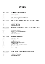


INDEX
SECTION 1
GENERAL INFORMATION
1.1.
Company Details
1.2.
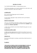
Important Notice
1.3.
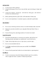
Mixer Operational and Safety Requirements
1.4
Installation Drawing
SECTION 2
INSTALLATION AND OPERATING INSTRUCTIONS
2.1.
Pre Installation Notes
2.2.
Installation Instructions
2.3.
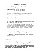
Operating Instructions
SECTION 3
TECHNICAL SPECIFICATION AND MAINTENANCE
3.1.
Technical Specification
3.2.
Shutdown Procedure and Maintenance
3.3.
Lubrication
3.4.
Gear Unit Maintenance
SECTION 4
MIXER SPARE PARTS
4.1.
Mixing Pan & Drive
4.2.
Mixing Star & Drive
4.3.
Mixing Star Assembly
4.4.
Mixing Star Lifting Arrangements
4.5.
Layout of Guards
4.6.
Micro Switch Cam & Proximity Switch
4.7.
Electrical Switch Gear
4.8.
Decals & Logos
SECTION 5
ANCILLIARY EQUIPMENT SPARE PARTS
5.1
Pan Trolley Four Wheels
5.2
MoD Additional Parts
Summary of Contents for CUMFLOW RP50XD MK2
Page 4: ...OPERATING AND MAINTENANCE MANUAL SECTION 1 GENERAL INFORMATION RP50XD MK2...
Page 12: ...OPERATING AND MAINTENANCE MANUAL SECTION 2 INSTALLATION AND OPERATING INSTRUCTIONS...
Page 20: ...OPERATING AND MAINTENANCE MANUAL SECTION 3 TECHNICAL SPECIFICATION AND MAINTENANCE...
Page 27: ...LUBRICATION CHART...
Page 28: ...OPERATING AND MAINTENANCE MANUAL SECTION 4 MIXER SPARE PARTS...
Page 29: ...RP50XD MK2 MIXING PAN DRIVE...
Page 32: ...RP50XD MK2 STAR DRIVE ASSEMBLY ASSEMBLED LENGTH OF COUPLING ITEM 3 ON SHAFTS IS 73MM...
Page 36: ...RP50XD MK2 MIXING STAR ASSEMBLY...
Page 38: ...RP50XD MK2 MIXING STAR LIFTING ARRANGEMENT...
Page 40: ...RP50XD MK2 COVERS GUARDS...
Page 43: ...PAGE INTENTIONALLY BLANK...
Page 47: ...RP50XD MK2 DECALS AND LOGOS CROKER CUMFLOW RP50XD 1 2 4 5 6 7 8 9 10 11 12 13...
Page 49: ...OPERATING AND MAINTENANCE MANUAL SECTION 5 ANCILLARY EQUIPMENT SPARE PARTS...
Page 50: ...RP50XD MK2 FOUR WHEEL PAN TROLLEY...
Page 53: ...OPERATING AND MAINTENANCE MANUAL SECTION 6 ELECTRICAL SYSTEM...
Page 55: ...Electrical Control Circuits dwg 11 03 02 10 55 09 Scaled to fit...
Page 56: ...V06302 dwg 11 12 02 07 03 44 Scaled to fit...
Page 57: ......
Page 58: ...Electrical Power Circuits dwg 11 03 02 10 58 17 Scaled to fit...
Page 59: ...V06303 dwg 11 12 02 07 04 45 Scaled to fit...
Page 60: ......
Page 61: ...General details of Control Panel dwg 11 03 02 11 01 09 Scaled to fit...
Page 62: ...V06301 dwg 11 12 02 07 02 37 Scaled to fit...
Page 63: ......
Page 64: ...Material Parts List dwg 11 03 02 11 03 32 Scaled to fit...
Page 65: ...V063PL1 dwg 11 12 02 07 01 06 Scaled to fit...
Page 66: ......
Page 67: ...OPERATING AND MAINTENANCE MANUAL SECTION 7 MISCELLANEOUS...