background image

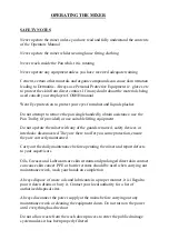
START PROCEDURE CROKER RP50XD, RP100XD &

RP150XD  RANGE MIXERS

1) Raise the mixing star assembly by way of the large hand wheel, rotate the wheel in a
clockwise direction to raise the star assembly

2) Ensure the mixing pan is in place on the pan rack (gear) and correctly seated down.

3) Turn the power on at the red isolator switch on the control panel

4) Ensure the red emergency stop plunger on the front of the control panel is not
depressed.

5) Press the green start button.

6) With both hands on the hand wheel, rotate the hand wheel anti-clockwise and lower
the mixing star slowly and gently down into the mixing pan. The motors driving the pan
and star should start automatically as the star enters the pan.

Note: do not allow the mixing star assembly to drop in an uncontrolled manner into
the mixing pan, lower it slowly with both hands on the hand wheel.

Summary of Contents for CUMFLOW RP50XD MK2

Page 1: ...ER PARTS OPERATION MANUAL WINGET LIMITED PO BOX 41 EDGEFOLD INDUSTRIAL ESTATE PLODDER LANE BOLTON LANCS BL4 OLS Tel 44 0 1204 854650 Fax 44 0 1204 854663 crokersales winget co uk parts winget co uk se...

Page 2: ...ION 3 TECHNICAL SPECIFICATION AND MAINTENANCE 3 1 Technical Specification 3 2 Shutdown Procedure and Maintenance 3 3 Lubrication 3 4 Gear Unit Maintenance SECTION 4 MIXER SPARE PARTS 4 1 Mixing Pan Dr...

Page 3: ...fer from your machine Winget Limited can accept no responsibility for incorrectly supplied parts unless the machine serial number part number and a full description of the items required is given when...

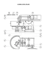
Page 4: ...OPERATING AND MAINTENANCE MANUAL SECTION 1 GENERAL INFORMATION RP50XD MK2...

Page 5: ...get co uk parts winget co uk service winget co uk ORDERING SPARES To help us to complete your order promptly and correctly we need Machine type and serial number Description and quantity of parts requ...

Page 6: ...t be modified in any way and only replaced with GENUINE CROKER spares obtained from WINGET LIMITED A daily check is advisable to ensure that the Blades Wearing parts are secure and undamaged MAXIMUM B...

Page 7: ...RS ACCEPT NO RESPONSIBILITY FOR ANY MODIFICATIONS MADE AFTER THE MACHINE HAS LEFT THE FACTORY UNLESS PREVIOUSLY AGREED IN WRITING THE MANUFACTURERS WILL ACCEPT NO LIABILITY FOR DAMAGE TO PROPERTY PERS...

Page 8: ...ounted on supports of adequate strength and rigidity to prevent undue vibration when mixing and securely bolted 3 3 Mixer frame to be level on structure add packers as required 3 4 Check that pan is c...

Page 9: ...cedures detailed in your companies Heath and Safety Policy at all times 6 3 Ensure all storage bins containing materials to be mixed are isolated MAINTENANCE 7 1 Ensure that all maintenance is carried...

Page 10: ...utlining weights etc 8 7 Refer to Method Statement when installation and commissioning is responsibility of Croker Nett Weights Max kgs 9 1 RP50XD 800 RP1250XD 4840 RP100XD 900 RP1500XD 4980 RP200XD 1...

Page 11: ...INSTALLATION DRAWING OPERATING AND MAINTENANCE MANUAL SECTION 2 INSTALLATION AND OPERATING INSTRUCTIONS...

Page 12: ...OPERATING AND MAINTENANCE MANUAL SECTION 2 INSTALLATION AND OPERATING INSTRUCTIONS...

Page 13: ...sing certified lifting gear of suitable capacity by a competent person An outline drawing and bolt hold plan is normally sent prior to the despatch of the machine and will enable preparations to be ma...

Page 14: ...n rack and drive gear are in mesh Also check that all the blade clearances are in line with the maintenance instructions On connecting to the power supply the wiring diagram must be referred to Note i...

Page 15: ...n When the mixing pan is removed the mixer cannot be operated as the proximity switches need to sense the pan in position to complete the electrical circuit 7 On completion of the mixing cycle the rai...

Page 16: ...ble lifting equipment Do not operate the mixer with any of the guards removed safety devices or interlocks disconnected They are there to offer you some protection ensure they are correctly maintained...

Page 17: ...hat the wheels are equally spaced to each side of the mainframe chassis 6 Fully raise the Mixing Star by means of the handwheel and allow the pan to come to a complete stop Manually rotate the pan unt...

Page 18: ...n be easily and quickly positioned over the rack and lowered into place 9 On no account must attempts be made to engage the trolley with the mixer mainframe chassis unless the Star Drive is raised and...

Page 19: ...on the control panel 4 Ensure the red emergency stop plunger on the front of the control panel is not depressed 5 Press the green start button 6 With both hands on the hand wheel rotate the hand wheel...

Page 20: ...OPERATING AND MAINTENANCE MANUAL SECTION 3 TECHNICAL SPECIFICATION AND MAINTENANCE...

Page 21: ...Ph 60Hz and not 415V 3 Ph 50Hz as listed overleaf When ordering spares for the motors gearbox or control panel it is important that this is stated Star Drive Gearmotor Unit Specification USA Canada C...

Page 22: ...ally enclosed geared electric motor to suit 3 phase 50 cycles 380 420 volts a c supply Mixing star drive 2 2kw totally enclosed geared electric motor to suit 3 phase 50 cycles 380 420 volts a c supply...

Page 23: ...WEIGHTS UNLADEN 800kg approx Weight of additional pan 64kg approx PAN LIFTING TROLLEY RHS steel frame mounted on four industrial castors with tubular section handle...

Page 24: ...lable from WINGET LIMITED 4 Ensure all safety guards and interlocks are reinstated prior to operating the mixer 5 Main items of wear see Section 4 A Star Blades B Fixed Blade Access to mixing pan inte...

Page 25: ...0 litres cap NOTE Total Carter SP220 is a synthetic oil and should not be mixed with mineral oils such as Mobil Mobilgear 630 unless the gearbox is thoroughly flushed out after draining INSPECT AND AD...

Page 26: ...as well as the cover lattice of the fan bonnet should be kept clean in order not to endanger the cooling of the motor with dust and dirt Although the bearings of the motor have life time lubrication...

Page 27: ...LUBRICATION CHART...

Page 28: ...OPERATING AND MAINTENANCE MANUAL SECTION 4 MIXER SPARE PARTS...

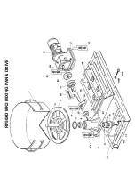
Page 29: ...RP50XD MK2 MIXING PAN DRIVE...

Page 30: ...Ph 60Hz and not 415V 3 Ph 50Hz as listed overleaf When ordering spares for the motors gearbox or control panel it is important that this is stated Star Drive Gearmotor Unit Specification USA Canada C...

Page 31: ...TERNATIVE 1 2 X 7 16 X6 CUT TO SIZE 1 15 CR460022 BEVEL PINION 1 16 CR150925 BEVEL PINION SHAFT BEARING 1 16A 176S01 COVER NIPPLE GREASE 1 16B 7S06 NUT M16 2 16C 11S06P SCREW SET M16 X 80 2 17 8S05J B...

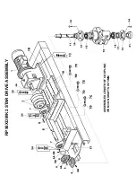
Page 32: ...RP50XD MK2 STAR DRIVE ASSEMBLY ASSEMBLED LENGTH OF COUPLING ITEM 3 ON SHAFTS IS 73MM...

Page 33: ...Ph 60Hz and not 415V 3 Ph 50Hz as listed overleaf When ordering spares for the motors gearbox or control panel it is important that this is stated Star Drive Gearmotor Unit Specification USA Canada C...

Page 34: ...M16 X 70 4 7D 7S06 NUT M16 6 7E 11S06K SCREW SET M16 X 60 2 8 CR460024 GEAR BEVEL 2 8A 57S05D2 GRUB SCREW M8 6 8B 555116600 PLATE GEAR RETAINING 2 8C 11S04D SCREW SET M10 X 30 2 8D 17S05 WASHER SPRIN...

Page 35: ...ER TAPER M12 4 24C 61S05 NUT BINX M12 4 25 11S04G SCREW SET GEAR MOTOR UNIT M10 X 45 4 25A 17S05 WASHER SPRING M10 4 25B 267S06 WASHER FLAT M10 4 26 CR26100867 STAR ARM CHASSIS FRAME 1 RP50XD MK2 STAR...

Page 36: ...RP50XD MK2 MIXING STAR ASSEMBLY...

Page 37: ...E M12 X 65 4 22A 267S07 WASHER FLAT M12 8 22B 17S06 WASHER SPRING M12 4 22C 7S05 NUT M12 4 26 CR260388 FINGER STAR BLADE 2 28 CR210142 BRACKET FIXED BLADE 1 28A 333104020 NIPPLE GREASE 1 4 BSP STRAIGH...

Page 38: ...RP50XD MK2 MIXING STAR LIFTING ARRANGEMENT...

Page 39: ...4 CR20100874 CHAIN TILTING 1 14A 134104002 LINK SPLIT CHAIN 1 15 CR200134 BOLT BLOCK DRAW CHAIN 1 16 CR200072 LINK ATTACHMENT CHAIN END 1 17 304712863 KEY PLATE WHEEL BUSH M12 X 8 X 63 1 18A 176S01 CO...

Page 40: ...RP50XD MK2 COVERS GUARDS...

Page 41: ...00897 COVER INSPECTION HOUSING SIDE R H NOT ILLUS 1 6A 11S03B SCREW SET M8 X 20 4 6B 17S04 WASHER SPRING M8 4 6C 267S05 WASHER FLAT M8 4 6D CR53100909 COVER INSPECTION HOUSING SIDE L H NOT ILLUS 1 6E...

Page 42: ...ER SIDE RH 1 13A CR54100912 GUARD PAN COVER SIDE LH 1 13B CR54100913 GUARD PAN COVER REAR NOT ILLUSTRATED 1 13C 11S03B SCREW SET M8 X 20 21 13D 17S04 WASHER SPRING M8 21 13E 267S05 WASHER FLAT M8 21 1...

Page 43: ...PAGE INTENTIONALLY BLANK...

Page 44: ...FTING 1 9 11S02C SCREW SET M6 X 25 2 10 17S03 WASHER SPRING M6 2 11 267S04 WASHER FLAT M6 2 12 CR54100863 BRACKET PROXIMITY SWITCH PAN 2 13 11S03C SCREW SET M8 X 25 4 14 267S05 WASHER FLAT M8 4 15 17S...

Page 45: ...Ph 60Hz and not 415V 3 Ph 50Hz as listed overleaf When ordering spares for the motors gearbox or control panel it is important that this is stated Star Drive Gearmotor Unit Specification USA Canada C...

Page 46: ...UE 8 5 144799000 CABLE 1 5MM SQ G Y 6491X H07 4MT 6 144700100 CABLE 1 5MM SQ RED 6491X H07 4MT 7 144798000 CABLE 1 5MM SQ BLACK 6491X H07 4MT 8 CR229103 CABLE 2 5MM SQ RED 6491X H07 3MT 9 CR229104 CAB...

Page 47: ...RP50XD MK2 DECALS AND LOGOS CROKER CUMFLOW RP50XD 1 2 4 5 6 7 8 9 10 11 12 13...

Page 48: ...2003665 DECAL SLING POINT 4 6 V2003598 DECAL BRITISH MADE 2 7 V2004307 DECAL ELECTRICAL HAZARD 2 8 V2004223 DECAL CE MARK 1 9 V2004229 DECAL OPERATORS HANDBOOK 2 10 V2004744 DECAL EYE PROTECTION 2 11...

Page 49: ...OPERATING AND MAINTENANCE MANUAL SECTION 5 ANCILLARY EQUIPMENT SPARE PARTS...

Page 50: ...RP50XD MK2 FOUR WHEEL PAN TROLLEY...

Page 51: ...G M8 4 16B 61S03 NUT BINX M8 4 17 CR53100846 HANDLE TROLLEY 1 18 8S03E BOLT HANDLE RETAINING M8 x 45 2 19 61S03 NUT BINX M8 2 20 CR449001 CASTOR SWIVEL REAR ASSEMBLY 2 INDIVIDUAL WHEEL ITEMS AVAILABLE...

Page 52: ...ION 1 2 101S05D RIVET POP 4 3 V2005132 TOOL KIT 1 4 CR54100774 TOOL BOX 1 5 11S04B SCREW SET M10 2 6 17S05 WASHER SPRING M10 2 7 7S04 NUT M10 2 RP50XD MK2 ADDITIONAL PARTS REQUIREMENT MoD ADDITIONAL P...

Page 53: ...OPERATING AND MAINTENANCE MANUAL SECTION 6 ELECTRICAL SYSTEM...

Page 54: ...Ph 60Hz and not 415V 3 Ph 50Hz as listed overleaf When ordering spares for the motors gearbox or control panel it is important that this is stated Star Drive Gearmotor Unit Specification USA Canada C...

Page 55: ...Electrical Control Circuits dwg 11 03 02 10 55 09 Scaled to fit...

Page 56: ...V06302 dwg 11 12 02 07 03 44 Scaled to fit...

Page 57: ......

Page 58: ...Electrical Power Circuits dwg 11 03 02 10 58 17 Scaled to fit...

Page 59: ...V06303 dwg 11 12 02 07 04 45 Scaled to fit...

Page 60: ......

Page 61: ...General details of Control Panel dwg 11 03 02 11 01 09 Scaled to fit...

Page 62: ...V06301 dwg 11 12 02 07 02 37 Scaled to fit...

Page 63: ......

Page 64: ...Material Parts List dwg 11 03 02 11 03 32 Scaled to fit...

Page 65: ...V063PL1 dwg 11 12 02 07 01 06 Scaled to fit...

Page 66: ......

Page 67: ...OPERATING AND MAINTENANCE MANUAL SECTION 7 MISCELLANEOUS...

Page 68: ...7 1 NOISE DETAILS Measured in accordance with Article V of Directive 2000 14 EC Noise Emission in the Environment by Equipment for Use Outdoors the noise levels should not exceed 105Lwa...

Reviews: