8.2
Mixer star blades to be checked daily for damage.
8.3
Pan rim and base wearing plates must be replaced before excessive wear causes
distortion.
8.4
Ensure mixing pan is rotating concentrically and pan base is rotating in
horizontal plane.
8.5
Mixer must not be stopped and started when there is mix in the pan.
8.6
Refer to the Contract Drawing for scope of supply and the Site instruction notes
outlining weights etc.
8.7
Refer to Method Statement when installation and commissioning is
responsibility of Croker.
Nett Weights Max (kgs)
9.1 RP50XD
800
RP1250XD 4840
RP100XD 900
RP1500XD 4980
RP200XD 1400
RP3000XD 7112
RP400XD 2000
FP1000
4040
RP550XD 2150
FP1500
4065
RP850XD 2600
FP2000
4100
9.2
Refer to technical specification for nett weights of ancillary equipment.
9.3
Refer to contract drawing for nett weights of ancillary equipment.
Miscellaneous
10.1
Noise. Measured in accordance with Article V of Directive 2000/14/EC
Noise Emission in the Environment by Equipment for Use Outdoors:- 105Lwa
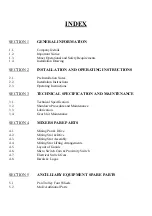
Summary of Contents for CUMFLOW RP50XD MK2
Page 4: ...OPERATING AND MAINTENANCE MANUAL SECTION 1 GENERAL INFORMATION RP50XD MK2...
Page 12: ...OPERATING AND MAINTENANCE MANUAL SECTION 2 INSTALLATION AND OPERATING INSTRUCTIONS...
Page 20: ...OPERATING AND MAINTENANCE MANUAL SECTION 3 TECHNICAL SPECIFICATION AND MAINTENANCE...
Page 27: ...LUBRICATION CHART...
Page 28: ...OPERATING AND MAINTENANCE MANUAL SECTION 4 MIXER SPARE PARTS...
Page 29: ...RP50XD MK2 MIXING PAN DRIVE...
Page 32: ...RP50XD MK2 STAR DRIVE ASSEMBLY ASSEMBLED LENGTH OF COUPLING ITEM 3 ON SHAFTS IS 73MM...
Page 36: ...RP50XD MK2 MIXING STAR ASSEMBLY...
Page 38: ...RP50XD MK2 MIXING STAR LIFTING ARRANGEMENT...
Page 40: ...RP50XD MK2 COVERS GUARDS...
Page 43: ...PAGE INTENTIONALLY BLANK...
Page 47: ...RP50XD MK2 DECALS AND LOGOS CROKER CUMFLOW RP50XD 1 2 4 5 6 7 8 9 10 11 12 13...
Page 49: ...OPERATING AND MAINTENANCE MANUAL SECTION 5 ANCILLARY EQUIPMENT SPARE PARTS...
Page 50: ...RP50XD MK2 FOUR WHEEL PAN TROLLEY...
Page 53: ...OPERATING AND MAINTENANCE MANUAL SECTION 6 ELECTRICAL SYSTEM...
Page 55: ...Electrical Control Circuits dwg 11 03 02 10 55 09 Scaled to fit...
Page 56: ...V06302 dwg 11 12 02 07 03 44 Scaled to fit...
Page 57: ......
Page 58: ...Electrical Power Circuits dwg 11 03 02 10 58 17 Scaled to fit...
Page 59: ...V06303 dwg 11 12 02 07 04 45 Scaled to fit...
Page 60: ......
Page 61: ...General details of Control Panel dwg 11 03 02 11 01 09 Scaled to fit...
Page 62: ...V06301 dwg 11 12 02 07 02 37 Scaled to fit...
Page 63: ......
Page 64: ...Material Parts List dwg 11 03 02 11 03 32 Scaled to fit...
Page 65: ...V063PL1 dwg 11 12 02 07 01 06 Scaled to fit...
Page 66: ......
Page 67: ...OPERATING AND MAINTENANCE MANUAL SECTION 7 MISCELLANEOUS...

