background image

Maintenance

5552

2/A1

RT-flex58T-D

Winterthur Gas & Diesel Ltd.

 3/ 11

3.

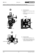
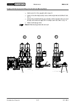
Removal of bearing shells

Loosen elastic screws 7 to bearings No. 2 3 4 and remove the bearing
covers (Fig. ’C’).

Place assembly template 94567 on an upper bearing shell (Fig. ’D’).

Press camshaft 12 accordingly by means of wooden underlay ’HU’ so that the

upper bearing shell can be turned downwards with the assembly template at

the same time (Fig. ’E’).

Remove the assembly template, the relevant bearing shell and then all other

ones.

Remark:

 Mark bearing shells after removal!

D

012.982/05

012.983/05

I

I

II

II

I

I

X

94567

HU

I - I

II-II

7

17

94567

E

12

Supply Unit: Removal and Fitting of Camshaft and Bearing Shells

V2 / 2013

Summary of Contents for WARTSILA RT-flex58T-D

Page 1: ... Vessel Type Engine No Document ID DBAC351676 Winterthur Gas Diesel Ltd 24hrs Support Schützenstrasse 1 3 Wärtsilä Services Switzerland Ltd CH 8400 Winterthur Zürcherstrasse 12 Switzerland CH 8400 Winterthur Switzerland 41 52 262 80 10 technicalsupport chts wartsila com ...

Page 2: ...e copyright holder Wärtsilä Services Switzerland Ltd makes no representation warranty express or implied in this publication and assumes no responsibility for the correctness errors or omissions for infor mation contained herein Information in this publication is subject to change without notice NO LIABILITY WHETHER DIRECT INDIRECT SPECIAL INCIDENTAL OR CONSEQUEN TIAL IS ASSUMED WITH RESPECT TO TH...

Page 3: ... Vessel Type Engine No Document ID DBAC351676 Winterthur Gas Diesel Ltd 24hrs Support Schützenstrasse 1 3 Wärtsilä Services Switzerland Ltd CH 8400 Winterthur Zürcherstrasse 12 Switzerland CH 8400 Winterthur Switzerland 41 52 262 80 10 technicalsupport chts wartsila com ...

Page 4: ...e copyright holder Wärtsilä Services Switzerland Ltd makes no representation warranty express or implied in this publication and assumes no responsibility for the correctness errors or omissions for infor mation contained herein Information in this publication is subject to change without notice NO LIABILITY WHETHER DIRECT INDIRECT SPECIAL INCIDENTAL OR CONSEQUEN TIAL IS ASSUMED WITH RESPECT TO TH...

Page 5: ...rom 10 to 30 seconds Sec 5 revised Remark concerning IMO technical file and detail of nozzle type added x 3103 1 A1 Measuring Crank Deflection 1 General aspects 2 Condition of measuring and 4 Crank deflection limits revised x 3425 1 A1 Piston Rings Four Piston Rings Determination of wear rate of chrome ceramic piston rings and measuring piston ring grooves introduced x 3425 1 A2 Piston Rings Three...

Page 6: ...5 08 EAAD086016 Pre Tesnioning jacks New jack for Cyl Cover studs x 9403 5 A1 30 2015 08 EAAD085234 Tool List Tool numbers 94871 and 94871A added new cyl Cover press GF94215A x Date of publication 2016 02 17 2751 2 A1 2018 WinGD Input Exhaust Valve Disassemble and Assemble Pge 7 Paragraph 3 4 Procedure changed x 5552 5 A1 2018 02 Wartsila Input Lubrication of Supply Unit during Maintenance Procedu...

Page 7: ...or Starting Air Crankshaft Connecting Rod and Piston Cylinder Liner and Cylinder Cover Bedplate and Tie Rod General Information Supply Unit Injection and Exhaust Valve Control Scavenge Air Receiver and Auxiliary Blower Cylinder Lubrication Piping Crank Angle Sensor Unit Tools ...

Page 8: ...Intentionally blank ...

Page 9: ...uide 6 7 Cylinder Liner 8 9 Piston Rod Gland 10 11 Exhaust Valve 12 13 Top and Bottom End Bearings to Connecting Rod 14 15 Piston Cooling and Crosshead Lubricating Link 16 17 Piston and Piston Rings 18 19 Driving Wheels for Supply Unit 20 21 Supply Unit 22 23 Fuel Pump 24 25 o Tightening Values of Important Screwed Connections 0352 1 A1 of Standard Screwed Connections 0352 2 A1 Masses Weights Indi...

Page 10: ...Intentionally blank ...

Page 11: ...nsidered therein It must be recognized that such data instructions and graphical illustrations may be subject to changes due to further development widened experience or any other reason This manual is primarily intended for use by the engine operating and maintenance personnel It must be ensured that it will always be at the disposal of such person nel for the operation of the engines and or for ...

Page 12: ...Intentionally blank ...

Page 13: ...the following main chapters General guidelines for maintenance Clearance tables tightening values of screwed connections masses weights seal rings Maintenance schedule Design groups Tool lists A few explanations to the above The General Guidelines for Maintenance contain in addition to recommen dations on precautionary measures to be taken also suggestions for carrying out the work The above menti...

Page 14: ...Intentionally blank ...

Page 15: ... 3 Crankshaft and Main Bearing 4 5 Crosshead Guide 6 7 Cylinder Liner 8 9 Piston Rod Gland 10 11 Exhaust Valve 12 13 Top and Bottom End Bearings to Connecting Rod 14 15 Piston Cooling and Crosshead Lubricating Link 16 17 Piston and Piston Rings 18 19 Driving Wheels for Supply Unit 20 21 Supply Unit 22 23 Fuel Pump 24 25 o Tightening Values of Important Screwed Connections 0352 1 A1 of Standard Scr...

Page 16: ...Removing the Wear Ridge Re dressing Lubricating Grooves and Scavenge Ports 2124 3 A1 Lubricating Quill with Pulse Jet Lubrication Removal and Fitting 2138 1 A2 Piston Rod Gland Dismantling and Assembling Measuring the Wear 2303 1 A1 o Cylinder Cover Removal and Fitting of Cylinder Cover and Water Guide Jacket 2708 1 A1 Loosening and Tensioning of Cylinder Cover Elastic Studs 2708 2 A1 Machining of...

Page 17: ...g of Top End Bearing 3303 3 A1 Removal and Fitting 3303 4 A1 Removal of Bearing Cover to Top End Bearing 3303 5 A1 o Crosshead Checking the Clearances and Fitting the Guide Shoes 3326 1 A1 Removal and Fitting of a Crosshead Pin 3326 2 A1 o Piston Removal and Fitting 3403 1 A1 Changing the Compression Shims 3403 2 A1 Dismantling and Assembling 3403 3 A1 Checking Piston Top Surface 3403 4 A1 o Pisto...

Page 18: ...Assembling 5612 1 A1 o Regulating Linkage Adjusting with Heinzmann StG 10 01 Actuator 5801 1 A1 Adjusting with Woodward ProAct II Analog Actuator 5801 1 A2 Scavenge Air Receiver and Auxiliary Blower Group 6 Scavenge Air Receiver Checking the Air Flaps and Cleaning the Scavenge Air Receiver 6420 1 A1 Auxiliary Blower Maintenance 6545 1 A1 o Scavenge Air Cooler Cleaning Water Side on Engine at Stand...

Page 19: ...mbling and Adjusting 9223 1 A1 Tools Explanation 9403 1 A1 Hydraulic Jacks and Pumps Arrangement and Application 9403 2 A1 o Hydraulic Pre tensioning Jacks Storing Servicing and Maintenance 9403 3 A1 General Application Instructions 9403 4 A1 o Tool List 9403 5 A1 Standard Tools Pages 1 32 Recommended Special Tools Pages 33 35 Special Tools Obtainable on Loan Pages 36 37 ...

Page 20: ...Intentionally blank ...

Page 21: ...rbocharger DRIVING END Cylinder Number FREE END Main Bearing Number Thrust Bearing Pads Rail Unit EXHAUST SIDE FUEL SIDE Supply Unit Counterclockwise Rotation Exhaust Waste Gate Option 6 5 4 3 2 1 7 1 2 3 4 5 Clockwise Rotation General Engine Numbering and Designations V2 2013 ...

Page 22: ...Actuator 3 Fuel Pump 1 Fuel Pump 2 Fuel Pump 3 Servo Oil Pump 2 Servo Oil Pump 1 013 149 05 013 150 05 Supply Unit FUEL SIDE DRIVING END Crank Angle Sensor Unit FREE END Sensor 2 GT5127C Sensor 1 GT5126C FUEL SIDE DRAWN FOR 7 8 CYLINDERS Crank Angle Sensor Unit GEAR WHEEL I I WCH02298 Engine Numbering and Designations 2013 08 V2 ...

Page 23: ...minate a person responsible for assigning work tasks to every person who is participating in maintenance work D Make sure that fluids or gases draining or escaping cannot cause accidents fires or explosions during maintenance work Keep the engine and the sur roundings clean Cleanliness increases the quality of the work and helps to prevent accidents Before beginning maintenance work on the diesel ...

Page 24: ...ked with all the clamps when ever the engine is running even if this is only for a short time in order to make temperature checks e g after changing bearings during an overhaul etc D In the case of a fire in the engine having been extinguished by means of CO2 the spaces affected must be well ventilated before work can be carried out within them Attention When performing electric welding near or on...

Page 25: ... by wood en pieces leather or special edge guards which are placed between the part and the rope or chain D Always use gloves a face shield and wear safety goggles when working with hydraulic tools D For your own safety keep away from under hanging loads never undersling hanging parts with your fingers or hands and never embrace lifting ropes with your hands D Removed parts must be secured in the ...

Page 26: ...ot to damage their thread They must be screwed in by hand until metal to metal contact is achieved Always use the specified lubricants on the threads D Adhere to tightening values wherever they are indicated Use the specified lubricant on the threads see 0352 1 and 0352 2 D Locking devices of bolts nuts etc must be fitted correctly and secured prop erly Use locking plates and locking wires only on...

Page 27: ... reasons D Determination of the weight of load D Determination of the suspension centres and weight distribution D Choice of attachment elements D Attaching and disconnecting 2 Attachment elements 2 1 Wire rope slings The lifting capacity of the wire rope slings is listed under their tool number in Tools List 9403 5 2 2 Span sets Span sets have the advantage of easy and simple handling The code an...

Page 28: ...oad is only permissible in the direction of the ring therefore the eye bolts or eye nuts must be brought to the right position if necessary by us ing distance rings D If there are through holes a washer should be placed from the opposite side under the nut or screw head D Whenever possible do not apply an angle of inclination bigger than 45 in all directions with regard to the ring level and espec...

Page 29: ...ightening the ring of the RUD eye bolt is freely rotatable the star profile wrench must be removed from the inner hexagon of the screw as shown in Fig A D Prior to loading the RUD eye bolt adjust it in force direction RUD eye bolts are not suitable to be turned under load D Lateral loading is permitted in no circumstances Fig B A FORCE DIRECTION Ring Star profile wrench Screw FORCE DIRECTION B 013...

Page 30: ...hose shackles may be used which are in accordance with American Stan dard RR C 271A or which fulfil or exceed these values including the safety factor All calculations for components and tools where shackles are used are laid out ac cordingly and based on the mentioned standards Normally the permissible lifting capacity of the shackles is specified for one single strand Attention If tools are comb...

Page 31: ...smooth surfaces e g tubes shafts D Protect the ropes against damages by providing a wooden pallet or a rag Sharp edges may even cut steel cables D If possible always tie down the load danger of fall D Wrapping the rope twice increases friction and adhesion in such a manner that even a smooth oily shaft is sliding less D Hemp rope strands wrapped around the hook prevent sliding Do not wrap steel ca...

Page 32: ...Intentionally blank ...

Page 33: ...olumn Maximum clearance dimension are such values as may be reached after a lengthy operating period which however may not be allowed to be exceeded or fall below On components where the clearance is ad justable by modifying the thickness of shims discs spacers etc the value given as Normal Clearance should always be arrived at or striven to attain Where this is not possible worn parts must be rep...

Page 34: ...Maintenance 0330 1 A1 RT flex58T D Winterthur Gas Diesel Ltd 2 25 1 3 2 WCH00997 003 319 00 Clearance Table Crankshaft and Thrust Bearing 2013 ...

Page 35: ... normal new mm Maximum clearance dimension due to wear mm 1132 Main bearing Bearing shell width 242 1 Lateral clearance per side 12 1203 1224 Thrust bearing Thrust bearing pad thickness 66 5 0 5 0 6 2 Thrust bearing clearance axial total 0 8 1 3 2 5 3 Thrust bearing pad lateral clearance per side 3 Clearance Table Crankshaft and Thrust Bearing 2013 ...

Page 36: ...Maintenance 0330 1 A1 RT flex58T D Winterthur Gas Diesel Ltd 4 25 1 2 003 318 00 003 318 00 MAIN BEARING No 1 MAIN BEARING No 2 AND FOLLOWING 1 2 Clearance Table Crankshaft and Main Bearing 2013 ...

Page 37: ...e to wear mm 1132 Main bearing No 1 Crankshaft outer 706 0 0 08 Main bearing inner 706 1 Bearing clearance vertical 0 3 0 7 0 9 1132 Main bearing No 2 and following Crankshaft outer 706 0 0 08 Main bearing inner 706 2 Bearing clearance vertical 0 2 0 6 0 8 All main bearing clearances are only valid with tie rods and main bearing studs tightened Clearance Table Crankshaft and Main Bearing 2013 ...

Page 38: ...Maintenance 0330 1 A1 RT flex58T D Winterthur Gas Diesel Ltd 6 25 EXHAUST SIDE 6 1 2 4 5 3 7 8 003 317 00 Clearance Table Crosshead Guide 2013 ...

Page 39: ...ransverse 990 0 20 0 31 3 Guide shoe clearance 0 20 0 90 1 1 4 Guide rail longitudinal 559 30 560 30 5 Guide rail lateral clearance total 0 60 1 80 2 2 6 Guide shoe lateral clearance longitudinal 0 20 0 40 7 Guide shoe bearing pin outer 330 0 03 0 06 Guide shoe bearing bore inner 330 0 057 0 8 Bearing clearance radial 0 03 0 117 0 25 For measuring the clearances see instructions in group 3326 1 Cl...

Page 40: ...Maintenance 0330 1 A1 RT flex58T D Winterthur Gas Diesel Ltd 8 25 WCH01000 1 2 3 4 5 Approx 96 150 mm Clearance Table Cylinder Liner 2013 V2 ...

Page 41: ... cylinder cover Water guide jacket Ø 880 0 60 0 40 1 Clearance total 0 70 1 10 Water guide jacket Ø 810 0 80 0 60 2 Clearance total 0 90 1 30 2124 Water guide jacket on cylinder liner Water guide jacket Ø 840 0 20 0 3 Clearance total 0 20 0 60 Water guide jacket Ø 801 0 60 0 40 4 Clearance total 0 60 1 0 2124 Cylinder liner 5 Cylinder liner bore radial 580 584 Pay attention to measuring point Clea...

Page 42: ...Maintenance 0330 1 A1 RT flex58T D Winterthur Gas Diesel Ltd 10 25 4 1 1 4 5 6 3 1 2 006 097 99 6 6 012 153 04 Clearance Table Piston Rod Gland 2013 ...

Page 43: ...ear mm 2303 Piston rod gland 1 Ring width radial 31 min 25 2 Ring width radial 24 min 22 20 3 Ring width radial 5 min 3 20 4 Ring clearance axial 0 05 0 16 0 50 5 Ring clearance axial 0 05 0 13 0 40 6 Ring clearance axial 0 10 0 17 0 40 Ring wear The differential value between nominal dimension and max wear is equal for all rings i e also for undersize rings Clearance Table Piston Rod Gland V2 201...

Page 44: ...Maintenance 0330 1 A1 RT flex58T D Winterthur Gas Diesel Ltd 12 25 L LENGTH VALVE SPINDLE GUIDE BUSH 1 3 L 2 3 L 3 2 1 003 316 00 003 316 00 Clearance Table Exhaust Valve 2013 ...

Page 45: ...ng direction method of measuring Nominal dimension normal new mm Maximum clearance dimension due to wear mm 2751 Valve spindle 1 Spindle outer 56 0 19 0 23 55 4 2751 Guide bush 2 Bore inner 56 0 03 0 56 3 3 Bore inner 56 0 03 0 57 0 Pay attention to measuring point Clearance Table Exhaust Valve 2013 ...

Page 46: ...intenance 0330 1 A1 RT flex58T D Winterthur Gas Diesel Ltd 14 25 10 mm 10 mm 10 mm 10 mm 6 7 6 7 2 3 2 3 4 4 8 5 1 003 315 00 003 315 00 Clearance Table Top and Bottom End Bearings to Connecting Rod 2013 ...

Page 47: ...nner 580 1 Bearing clearance vertical 0 31 0 55 0 75 2 Lateral clearance total 0 41 0 57 3 Lateral clearance total 0 31 0 48 4 Axial clearance per side 0 2 0 4 1 2 3303 Bottom end bearing Crankshaft outer 706 0 0 08 Bearing inner 706 5 Bearing clearance vertical 0 45 0 65 0 8 6 Lateral clearance total 0 60 0 80 7 Lateral clearance total 0 60 0 80 8 Axial clearance total 17 Pay attention to measuri...

Page 48: ...Maintenance 0330 1 A1 RT flex58T D Winterthur Gas Diesel Ltd 16 25 4 1 1 3 1 3 3 2 3 2 2 003 314 00 4 003 314 00 Clearance Table Piston Cooling and Crosshead Lubricating Link 2013 ...

Page 49: ... Nominal dimension normal new mm Maximum clearance dimension due to wear mm 3603 Piston cooling and crosshead lu bricating link Pin outer 55 1 Bearing clearance radial 0 03 0 09 0 20 2 Bearing width 146 3 Lateral clearance total min 1 0 4 Lateral clearance total 2 0 Clearance Table Piston Cooling and Crosshead Lubricating Link 2013 ...

Page 50: ... RT flex58T D Winterthur Gas Diesel Ltd 18 25 8 8 1 10 2 9 5 3 4 8 8 1 10 2 9 5 3 4 EXECUTION WITH THREE PISTON RINGS EXECUTION WITH FOUR PISTON RINGS 6 7 7 6 B A B A B A B A Clearance Table Piston and Piston Rings 2013 08 ...

Page 51: ...vertical 16 0 35 0 30 5 Groove depth radial 19 50 3425 Piston rings Ring height vertical 16 0 0 03 Point A Point B 6 Ring clearance vertical 0 35 0 43 0 60 0 75 7 Ring clearance vertical 0 30 0 38 0 55 0 70 8 Ring width radial 19 0 25 3403 Piston skirt 9 Skirt outer 579 2 0 0 2 min 578 3403 Piston rod 10 Rod outer 220 0 050 0 096 min 219 3 Used piston rings may be refitted if they will keep within...

Page 52: ...Maintenance 0330 1 A1 RT flex58T D Winterthur Gas Diesel Ltd 20 25 WCH01002 1 2 1 3 4 2 WCH01003 Clearance Table Driving Wheels for Supply Unit 2013 V2 ...

Page 53: ...e dimension due to wear mm 4103 Intermediate wheel Shaft outer 160 1 Bearing clearance vertical 0 08 0 15 0 25 2 Axial clearance total 0 6 1 1 1 5 3 Tooth backlash 0 28 0 45 0 65 4 Tooth backlash 0 20 0 34 0 55 When measuring the tooth backlash pay attention to the tooth crowning of the tooth flanks in longitudinal direction Clearance Table Driving Wheels for Supply Unit V2 2013 ...

Page 54: ...Maintenance 0330 1 A1 RT flex58T D Winterthur Gas Diesel Ltd 22 25 8 5 4 6 1 3 2 7 WCH00992 Clearance Table Supply Unit 2013 V2 ...

Page 55: ...ply unit 1 Pinion outer 80 0 0 019 Bearing fitted inner 80 0 10 0 058 2 Bearing clearance radial 0 058 0 119 3 Axial clearance total 0 25 0 54 0 7 5552 Camshaft unit 4 Cam shaft outer 120 0 0 022 5 Bearing clearance radial 0 10 0 19 6 Axial clearance total 0 2 0 5 0 7 7 Tooth backlash 0 12 0 22 8 Minimum clearance 2 Minimum clearance between cam and roller with fuel pump cut out Clearance Table Su...

Page 56: ...Maintenance 0330 1 A1 RT flex58T D Winterthur Gas Diesel Ltd 24 25 012 098 04 3 8 7 6 1 2 4 5 171 mm A B C 013 032 05 PLUNGER CYLINDER 30 mm Ø30 35 mm 38 mm Ø36 mm Clearance Table Fuel Pump 2013 ...

Page 57: ... 0 027 Guide piston outer 130 Lower housing inner 130 2 Clearance radial 0 070 0 125 0 15 3 Thrust piece lower spring carrier axial 0 02 0 06 0 08 5556 Roller guide Bush outer 60 Roller inner 60 4 Clearance radial 0 03 0 09 0 1 Pin outer 50 Bush inner 50 5 Clearance radial 0 025 0 080 0 1 Pin outer 50 Guide piston bore inner 50 6 Clearance radial 0 009 0 050 0 08 7 Axial clearance of bush total 0 ...

Page 58: ...Intentionally blank ...

Page 59: ...ison only When using other hydraulic jacks the required pressure in bar must be calculated in relation to the effective jack piston surface Conversion factor 1 Nm 0 102 mkp 1 bar kp cm2 D The relevant lubricant has to be applied to threads and seating surfaces if no other instructions are mentioned D Bostik Findley Inc USA is manufacturer of Never Seez NSBT 8 V2 2013 Tightening Values of Important...

Page 60: ...Maintenance 0352 1 A1 RT flex58T D Winterthur Gas Diesel Ltd 2 7 WCH00985 2013 V2 Tightening Values of Important Screwed Connections ...

Page 61: ...Maintenance 0352 1 A1 RT flex58T D Winterthur Gas Diesel Ltd 3 7 Starting Air Valve Injection Valve Exhaust Valve WCH00985 WCH00985 WCH00985 V2 2013 Tightening Values of Important Screwed Connections ...

Page 62: ...Maintenance 0352 1 A1 RT flex58T D Winterthur Gas Diesel Ltd 4 7 Supply Unit I Servo Oil Rail WCH00989 WCH00985 Fuel Pump I I I I WCH00992 I 2013 V2 Tightening Values of Important Screwed Connections ...

Page 63: ...intenance 0352 1 A1 RT flex58T D Winterthur Gas Diesel Ltd 5 7 Injection Control Unit WCH00987 WCH00988 Fuel Rail Free End Fuel Rail Driving End Tightening Values of Important Screwed Connections V2 2013 ...

Page 64: ...Maintenance 0352 1 A1 RT flex58T D Winterthur Gas Diesel Ltd 6 7 High Pressure Fuel Pipe High Pressure Servo Oil Pipe WCH00990 WCH00991 Tightening Values of Important Screwed Connections 2013 V2 ...

Page 65: ...Maintenance 0352 1 A1 RT flex58T D Winterthur Gas Diesel Ltd 7 7 Rail Unit Transport Crank Angle Sensor Unit WCH00985 WCH00985 Tightening Values of Important Screwed Connections V2 2013 ...

Page 66: ...Intentionally blank ...

Page 67: ...on These tightening instructions are valid only if screws are made of the 8 8 material threads have been lubricated with oil Standard thread Fine thread Tightening torque Nm M8 M8 x 1 20 M10 M10 x 1 25 40 M12 M12 x 1 25 70 M14 M14 x 1 5 110 M16 M16 x 1 5 170 M18 M18 x 1 5 250 M20 M20 x 1 5 350 M22 M22 x 1 5 450 M24 M24 x 2 600 M27 M27 x 2 900 M30 M30 x 2 1200 M33 M33 x 2 1600 M36 M36 x 3 2100 M39 ...

Page 68: ...to the bottom of the tap hole and tighten Always utilize a bolt driver or two nuts Tools like a pipe wrench etc which would damage the bolt shank must never be used D For the protection of the elastic bolt in the cylinder block and cylinder cover fill the annular space above the thread with a non hardening jointing compound see 2751 1 TIGHTENING TORQUE FOR ELASTIC BOLTS TIGHTENING TORQUE Nm 400 30...

Page 69: ...linder liner 3390 2130 Water guide jacket 330 2303 Piston rod gland 129 2708 Elastic stud for valve cage Cylinder cover without accessories 20 1336 2722 Injection valve complete 12 2728 Starting air valve complete 30 2740 Indicator valve complete 2 2751 Exhaust valve with spindle complete 723 2754 Exhaust valve spindle 53 3 3103 Balance weight 335 870 3122 Flywheel Light middle weight heavy 2125 2...

Page 70: ...guide shoes Middle part with guide shoes complete complete 1213 1807 297 3403 Piston with piston rod Piston crown Piston skirt Piston rod complete 1437 350 62 909 3603 Toggle lever to piston cooling and crosshead lubrication complete 122 4 4106 Gear wheel on crankshaft Gear wheel on crankshaft 2 part complete 663 819 4120 Intermediate wheel with bearing pins and bearings for supply unit Bearing fo...

Page 71: ... MET60MA MB MET66MA MB TPL73 B TPL77 B 2000 3000 4900 7000 3550 2000 4260 4500 6250 6500 2600 4070 6545 Auxiliary blower with electric motor Electric motor complete 700 915 250 420 6606 Scavenge air cooler SAC245 Tier II SAC243 Tier II 1203 1803 6708 Water separator stainless steel 3 lips TPL73 MET53 TPL77 A170 A175 MET60 66 A180 200 175 225 8 8139 Expansion piece after exhaust valve DN 300 58 Ind...

Page 72: ...Intentionally blank ...

Page 73: ... with friction shims Check pre tension of waisted studs first time after sea trial 6000 8000 Op h 1903 1 Tie rod Check pre tension if necessary re tension first time after one year 24 000 30 000 Op h 2 2124 1 Cylinder liner Establish wear in bore in fitted condition at every piston removal 2124 2 Remove cylinder liner as required Replace O rings at every removal Replace soft iron joint ring betwee...

Page 74: ...lve General inspection of valve housing valve spindle and valve seat without dismantling of exhaust valve at every piston removal 2751 4 Check condition and wear of valve spindle if necessary regrind seat by machining 24 000 36 000 Op h Check piston seal ring air spring rod seal ring guide bush 24 000 36 000 Op h Check condition and wear of valve seat if necessary regrind seat by machining 24 000 ...

Page 75: ...lishing ring and chrome ceramic piston rings 18 000 36 000 Op H condition based Check tightness on piston in situ and with running oil pump visual check through scavenge ports after refitting 3403 3 Dismantling and assembling open cooling space clean same min one piston every three years as required 3403 4 Check condition of the piston top surface at every piston removal Visual check through scave...

Page 76: ... 000 Op h Camshaft check thrust bearing clearances 36 000 Op h 5556 1 Fuel pump Replace O rings in valve block 18 000 Op h Random visual check of plunger cylinder roller and roller guide 18 000 Op h 5562 1 Fuel pressure control valve PCV Check shut down function see Operating Manual 4003 1 Function check see Operating Manual 5562 1 3000 Op h 6000 Op h General overhaul only necessary when PCV fails...

Page 77: ...ing Manual Air filter Check filter half yearly Cleaning of filter at a np increase of 50 compared to the shop test value at same engine load see Operating Manual 6510 1 as required 6545 1 Auxiliary blower Clean impeller and casing 24 000 36 000 Op h Replace ball bearing 24 000 36 000 Op h 6606 1 Scavenge air cooler Cleaning of scavenge air cooler air side in service at the beginning weekly later a...

Page 78: ...rds every three months 8 8135 1 Exhaust Waste Gate LLT During a longer operation period at low engine load manually open butterfly valve at least once per week see Operating Manual 8135 1 General inspection according to instruction of valve manufacturer Servo oil automatic filter Follow manufacturer s instructions Starting air piping Drain de water before and after every manoeuvering period Pressu...

Page 79: ...k cracks and wear of tooted belt visually Visual lubricating oil check 3000 Op h Replace toothed belt 24 000 Op h Overhaul drive ball bearing sealing ring etc and check shaft eccentricity of CAS drive 48 000 Op h Check shaft eccentricity of CAS drive at every CAS exchange Replace crank angle sensor 48 000 Op h only if new soft belt is applied from beginning Oil mist detector Follow manufacturer s ...

Page 80: ...are see Operating Manual 0720 1 and 0760 1 Overhaul according to Maintenance Manual Genuine spare parts used Engine monitoring Engines according to specifications of Wärtsilä Switzerland Ltd On the engine sectional drawings 0803 1 those parts are marked with group numbers as they are found in the Maintenance Manual Group numbers exist of the following engine components although these parts are not...

Page 81: ...D Winterthur Gas Diesel Ltd 1 2 Cross Section 3326 1 3326 2 6545 1 5556 1 5562 1 2728 1 8460 1 8733 1 3301 1 4325 1 1112 1 6420 1 8447 1 6708 1 6606 1 6606 2 1903 1 5801 1 WCH00993 Engine Cross Section and Longitudinal Section V2 2013 ...

Page 82: ...inal Section 2303 1 1132 1 1132 2 1203 1 2138 1 2722 1 2751 1 to 2751 4 3140 1 9223 1 3303 1 to 3303 4 3403 1 to 3403 4 2124 1 to 2124 3 3103 1 3130 1 3130 2 2708 1 to 2708 3 3425 1 1224 1 8752 1 4103 1 to 4103 3 WCH00994 Engine Cross Section and Longitudinal Section 2013 V2 ...

Page 83: ...ds 1132 1 A1 Removal and Fitting of a Main Bearing 1132 2 A1 o Thrust Bearing Checking the Axial Clearance 1203 1 A1 Removal and Fitting the Thrust Bearing Pads 1224 1 A1 Engine Stays with Friction Shims Checking the Pre tension 1715 1 A1 Tie Rod Checking the Pre tension and Tensioning the Tie Rods 1903 1 A2 Bedplate and Tie Rod Group 1 Winterthur Gas Diesel Ltd RT flex58T D MM 2013 ...

Page 84: ...Intentionally blank ...

Page 85: ...KO Slot 9 Chock RS Round bar 10 Ship s foundation plate SA Gap 1 General The pre tension of the foundation bolts holding down studs must be checked at longer intervals e g during overhauls see 0380 1 In the area of the thrust bearing the foundation may be fastened with foundation bolts 2 and sleeves 5 Fig A or with foundation fitted studs 4 Fig B The remaining area is fastened with foundation bolt...

Page 86: ...e piston the maximum stroke of the piston is reached Therefore do not continue to operate the pre tensioning jack Check with feeler gauge through slot KO if there is any clearance between nut 6 and its seating If there is no clearance this means that the tightening condition of the founda tion bolt has remained unchanged since the last check The pressure can be released to zero with relief valve E...

Page 87: ...m stroke of the piston is reached Therefore do not continue to operate the pre tensioning jack Turn back nut 6 by one turn and release the pressure to zero Remove the pre tensioning jack E 002 853 99 12 13 11 94935A 94935 94934A 94934E 94931 EV 94932 6 KO 1 2 3 4 4 Tensioning of the foundation bolts D Tensioning of the foundation bolts must be carried out in two steps Tension all foundation bolts ...

Page 88: ...Intentionally blank ...

Page 89: ...Remark Pay attention to General Application Instructions 9403 4 for hydraulic pre tensioning jacks 2 Loosening the elastic studs Hook assembly tool 94114A into suspension holes 9 of double pre tensioning jacks 94114 and place the latter onto elastic studs 1 for the main bearing Fig C Connect both double pre tensioning jacks by HP hoses 94935 connection block 94934 and hydraulic distributor 94932 w...

Page 90: ...ic unit adjust the pressure to 1500 bar and keep it constant Mark the position of nuts 3 against bearing cover 1st step Fig A Tighten all nuts 3 with round bar RS until firmly seated TIGHTENING ANGLE 1ST STEP 2ND STEP 009 668 02 A y x y x 010 357 02 Using feeler gauge 94122 inserted in slot KO check if there is no clearance at hand between the nuts and the seating surfaces 2nd step No clearance mu...

Page 91: ...e 1132 1 A1 RT flex58T D Winterthur Gas Diesel Ltd 3 3 B C I I I I L 1 4 5 4 6 RS KO 011 310 03 9 3 7 GAP 0 mm 94942 8 94935 94934 94932 94114 98 7663 2 Main Bearing Loosening and Tensioning of Elastic Studs 2013 ...

Page 92: ...Intentionally blank ...

Page 93: ... tool 94130 1 Support 94141 hereafter called bearing cover 2 Ground plates 94141A bearing shell 2 Working platforms 94142 1 HP oil pump 94931 1 Hydr distributor 94932 1 Hydr distributor 94934A 1 HP hose 94935 2 HP hoses 94935A 2 Hydraulic jacks 94936 1 Hydraulic ram 94950 Overview 1 General 1 14 2 Placing of device 94111 2 14 3 Removal of main bearing cover 3 14 4 Turning out and removal of lower ...

Page 94: ...ce 94111 must always be used for removal and fitting of the bearing covers and handled carefully and not be changed as its arm lengths correspond to a spe cified dimension Eyelet 94120 must be used for the removal and fitting of the bearing cover No 1 Fit device 94111 onto bearing cover 2 as shown below Screw down lifting screw 5 fully onto the bearing cover There must be no clearance S between be...

Page 95: ...ring cover over the elastic bolts using rope 94120B and manual ratchet H1 Remark Oil bore 7 in bearing girder 6 must be closed off immediately after lifting the bearing cover to prevent any dirt from entering Fig A Remove the bearing cover from the column Connect ratchets H3 with rope 94120B and H2 and lift the bearing cover out of the flywheel area Carefully put the bearing cover in horizontal po...

Page 96: ...4120F to the column wall and lift the bearing cover 2 via roller support 94117 over the elastic studs Remark Oil bore 7 in bearing girder 6 must be closed off immediately after lifting the bearing cov er to prevent any dirt from entering Fig A Screw eye bolt RC into the bearing cover and connect it with rope 94120E to manual ratchet H4 Fig E Attach manual ratchet H2 with rope 94120G to lifting dev...

Page 97: ... Lift bearing cover 2 out of crankcase by means of manual ratchet H2 with rope 94120G and manual ratchet H4 Carefully put the bearing cover in horizontal position on wooden underlay WU Make sure the protruding bearing shell does not get damaged G H2 H4 94120 WU 2 10 FUEL SIDE 94120G WCH01010 Removal and Fitting of a Main Bearing V2 2013 ...

Page 98: ... toothing put a copper or aluminium plate between the ram and the flywheel Fig K 4 1 Placing of hydraulic jacks Turn corresponding crank to exhaust side approx 90_ after T D C Put support 94141 on two bearing girders 6 parallel to the engine axis Place hydraulic jacks 94936 on support 94141 Connect the hydraulic jacks with HP hoses 94935 and 94935A as well as hydr distributor 94934A to HP oil pump...

Page 99: ... the point where the neighboring main bear ings show no vertical clearance between upper bearing shells and crankshaft Keep pressure in the hydraulic jacks constant Measure again lateral bearing clearances y1 and y2 and compare the val ues with those from the 1st measurement as described above D If the lateral clearance has changed by more than 0 1 mm due to lifting of the crankshaft the latter mu...

Page 100: ...s of the bearing shell 3 to the other side and connect them with lifting yoke 94119 Remark By means of a wire attached to the ropes they can be pulled below the bearing journal to the other side Slowly turn out bearing shell using manual ratchet H1 from the bearing girder until both ends of the bearing shell are free no meshing check Remove lifting yoke Remark If a bearing shell jams during turnin...

Page 101: ...ell 3 Attach manual ratchet H2 and connect it to lifting device 94116 Lift bearing shell 3 as high as possible and move it to exhaust side Disconnect manual ratchet H1 with rope 94120B and reposition it to gallery support Move bearing shell using manual ratchets H2 and H1 out of column and place it carefully on platform L II 94116 II 94120B 3 94120B 3 H1 H2 H1 WCH01015 Removal and Fitting of a Mai...

Page 102: ...ke 94119 are mounted in the same way as described in paragraph 4 4 With manual ratchet H1 pull bearing shell slowly out from the bearing girder until both ends of the bearing shell are free no meshing check Remove lifting yoke Remark If a bearing shell jams during turning out lifting yoke 94119 must be fas tened to the two opposite wire ropes of turning out device 94118A Subsequently draw the bear...

Page 103: ...ft bearing shell up to roller support 94117 Connect rope 94120G to lifting tool 94116 and manual ratchet H2 Connect rope 94120E to lifting tool 94116 and manual ratchet H4 Take over bearing shell to manual ratchet H2 and manual ratchet H4 and disconnect manual ratchet H1 with rope 94120F Guide bearing shell out of column by means of manual ratchets H2 and H4 and place it carefully on platform N I ...

Page 104: ...94130 to clean the bearing bore For this purpose the round bar of the cleaning tool is to be wrapped in clean cloths then stuck between the bearing bore and the bearing journal of crankshaft 1 and by means of a wire rope pulled under the bearing journal to the other side Take care not to damage the running face of the bearing journal with the wire rope O 009 823 02 WIRE ROPE 94130 CLOTH WIRE ROPE ...

Page 105: ...ide 94115 P 94115 9 4 6 002 779 98 010 438 02 I I TURNING IN DIRECTION OF BEARING SHELL Fasten turning out device 94118 94118A to the front face of lower bearing shell 3 The two recesses in the turning out device must point towards the bearing shell rear side Thoroughly clean and lavishly oil both main bearing sides The bearing shell may be lifted onto the crankshaft with fitted lifting tool 94116...

Page 106: ... the crankcase The bearing clearances and the crank deflection must be measured after a new lower bearing shell has been fitted and the bearing cover has been tightened see 3103 1 7 Fitting of main bearing covers Fitting the bearing cover is carried out analogously to the removal but in the re verse sequence whereby attention must be paid to the following D Upper bearing shell 10 Fig A is placed i...

Page 107: ...s 2 Measuring method 2 Displace the crankshaft axially until it rests on the engine side thrust bearing pads AHEAD and then fix it in this position Measure the distance between the coupling flange and the upper part of the oil baffle with inside micrometer 94101 at the position indicated The amount by which distance X is smaller than that given on the sheet Check Dimen sions corresponds to the wea...

Page 108: ...3 1 A1 RT flex58T D Winterthur Gas Diesel Ltd 2 2 THRUST 0 8 1 3 mm 2 5 8 4a 7a 6 4 3 7 B 003 311 00 CHECK HOLE FOR FREE PASSAGE EVERY 6000 8000 OP HOURS 1 WCH01018 Thrust Bearing Checking the Axial Clearance 2013 V2 ...

Page 109: ... thrust bearing pads must all be replaced in their original position Note the numbering of the individual pads Also refer to the follow ing pages for the arrangement of thrust bearing pads on engines with fixed pitch propellers F P P and controllable pitch propellers C P P respectively For fitting the thrust bearing pads tools 94155 or 94155A respectively can also be utilized Note in this respect ...

Page 110: ...1 RT flex58T D Winterthur Gas Diesel Ltd 2 4 FUEL SIDE EXHAUST SIDE I I II II I I 4 2 2a 1 6 2 2a 5 3 1 2 2a 94155 A B 7 94155A 94155 94155A 003 309 00 003 309 00 003 309 00 Removal and Fitting the Thrust Bearing Pads 2013 ...

Page 111: ... PADS ON ENGINE SIDE VIEW FROM DRIVING END PADS AT DRIVING END AHEAD ASTERN CLOCKWISE ROTATING ENGINE ARRANGEMENT OF THRUST BEARING PADS FOR ENGINES WITH FIXED PITCH PROPELLER COUNTER CLOCKWISE ROTATING ENGINE PADS FOR AHEAD AHEAD ASTERN 003 685 95 PROPELLER THRUST AHEAD PROPELLER THRUST ASTERN Removal and Fitting the Thrust Bearing Pads 2013 ...

Page 112: ...NG END PADS ON ENGINE SIDE VIEW FROM DRIVING END PADS AT DRIVING END ARRANGEMENT OF THRUST BEARING PADS FOR ENGINES WITH CONTROLLABLE PITCH PROPELLER SUPPORT SURFACE AHEAD ASTERN AHEAD ASTERN COUNTER CLOCKWISE ROTATING ENGINE PADS FOR AHEAD 003 684 95 PROPELLER THRUST AHEAD PROPELLER THRUST ASTERN Removal and Fitting the Thrust Bearing Pads 2013 ...

Page 113: ...s 1 each are installed on the fuel side and at the free end of the engine Fig A The pre tension of screws 3 must be checked at specified intervals see 0380 1 Remark Pay attention to General Application Instructions 9403 4 for hydraulic pre tensioning jacks For checking the pre tension of the foundation bolts 1112 1 same jack 94145 is used and its nameplate engraved with 1000 bar Therefore special ...

Page 114: ...gauge through slot KO if there is any clearance between nut 4 and its seating If there is no clearance this means that the tensioning condition of the screw has remained unchanged since the last check The pressure can be released to zero and the pre tensioning jack removed Should a clearance be found nut 4 must be tightened down onto its seating with rod 94005D while the pressure is kept at 150 ba...

Page 115: ...or such checks it is not required to loosen the elastic studs of the main bearings nor the clamp screws 10 Fig D Remark Pay attention to General Application Instructions 9403 4 for hydraulic pre tensioning jacks 2 Checking the pre tension of tie rods Remove protection cover 8 from all tie rods and clean the contact face of inter mediate ring 2 Place both pre tensioning jacks GF 94180 onto two tie ...

Page 116: ...any clearance does exist tighten the nut with rod 94005F until it rests firmly on the intermediate ring Subsequently release the pressure to zero at the hy draulic unit If no clearance exists the pressure can immediately be released and the pre tensioning jacks removed Check all the tie rods in this manner and wherever necessary tighten the nut Protect the tie rod threads against corrosion by coat...

Page 117: ...minary works D Clamp screws 10 must not be tightened up D Lower tie rod nut 14 is screwed on Clean the seating surface for intermediate ring 2 and upper tie nut 3 and smear them with MOLYKOTE G paste Smear the tie rod thread lavishly with MOLYKOTE G paste and screw on up per tie nut with the marking TOP upwards check for easy threading Screw eye bolt into the tie rod and lift it carefully until th...

Page 118: ...the two upper tie rod nuts 3 with rod 94005F Never move pistons 5 of the pre tensioning jacks further up than to the red limiting grooves BN Measure again distance L and record it as L1 The tie rods are correctly tensioned with 1500 bar when the following reference value of a total elongation nL L1 L is measured nL 14 5 16 5 mm Release pressure to 0 Proceed in the same way following the required s...

Page 119: ... A2 RT flex58T D Winterthur Gas Diesel Ltd 5 5 III I III II I I I I 11 7 15 D 7 8 1 3 2 WCH00667 1 15 12 10 FLUSH AN 13 14 9 II I 16 Checking the Pre tension and Tensioning the Tie Rods with M80x6 Thread Diameter V2 2013 ...

Page 120: ...Intentionally blank ...

Page 121: ...8 1 A1 Loosening and Tensioning of Cylinder Cover Elastic Studs 2708 2 A1 Machining of Sealing Face for Injection Valve 2708 3 A1 Injection Valve Checking Dismantling Assembling and Adjusting 2722 1 A1 Starting Air Valve Removal Fitting and Dismantling Grinding in and Assembling2728 1 A1 Relief Valve for Cylinder Cover 2745 1 A1 o Exhaust Valve Removal and Fitting of Exhaust Valve Replacing of Ela...

Page 122: ...Intentionally blank ...

Page 123: ...ing wear ridge and the antipolishing ring The unrun position must be thoroughly cleaned from any deposits or lacquer before measurement Hook the measuring gauge over the top face of the cylinder liner The measurements have to be taken in longi tudinal and transversal directions to the en gine axis by putting the inside micrometer 94101 into the holes provided in the measur ing gauge For maximum pe...

Page 124: ...Intentionally blank ...

Page 125: ... Centring pin DP Depository for GF 94207 10 Cylinder cover WU Wooden underlay Overview 1 Preparatory works 1 7 2 Removal and fitting of cylinder liner 2 7 3 Removal and fitting of antipolishing ring 4 7 4 Removal and fitting of water guide jacket 5 7 5 Removal and fitting of insulation bandage 6 7 6 Laying down and raising cylinder liner 7 7 1 Preparatory works Drain cylinder cooling water from th...

Page 126: ... pieces press fit I 5 5 10 I A 3 2 17 6 18 8 7 19 3 WCH01000 2 1 Placing device GF 94201 Place the device GF 94201 with its lifting tool GF 94202 and all parts diagon ally onto cylinder liner 2 as shown below Apply copper paste to the threads of screws 16 and tighten them with 860 Nm Apply copper paste to the threads of special screws GF 94207 and tighten them with 300 Nm I I DP GF 94202M GF 94202...

Page 127: ... cylinder block 1 Apply a non hardening sealing compound Turn the cylinder liner 2 and align the centring hole in holder 14 with the cent ring pin 9 of the cylinder block 1 Lower the cylinder liner Fit the connection pieces 7 with transition tubes 6 to water guide jacket Fit all lubricating quills and connect their pipings Actuate the cylinder lubricating pump until oil emerges from all the lubric...

Page 128: ...and then it can be removed 3 2 Fitting Clean the seating surfaces on the antipolishing ring and cylinder liner Fit four suspension straps 94208 D Pay attention that one of the holes for fastening the suspension straps lies on fuel side Smear the antipolishing ring lightly with oil Fasten the ropes to the suspension straps and fit the antipolishing ring by means of the crane 4 D 94208 2 003 468 00 ...

Page 129: ...hets with the RUD eye bolts Loosen three screws 15 If necessary use them to separate the water guide jacket from the cylinder liner Lay down water guide jacket on the bottom plates by means of manual ratchets Lift cylinder liner and place it on the bottom plates 4 2 Fitting Fitting of the water guide jacket is carried out analogously to the removal but in reverse sequence Fit new O rings and oil t...

Page 130: ... 4 Loosen all tension springs 13 with assembly tool 94345E Remove the plate 12 for insulation bandage Remove the insulation bandage 11 5 2 Fitting Fitting of the insulation bandage is carried out analogously to the removal but in reverse sequence Make sure the insulation bandage overlaps approximately 34 mm 11 12 11 approx 34 mm FUEL SIDE WCH01020 I 13 11 II F II 11 Gap approx 5 mm I 12 Cylinder L...

Page 131: ...er liner following the sequence drawn below and secure it against rolling away by means of wooden underlays and wedges D Raising the cylinder liner is carried out in reversed sequence Risk of accident Laying down and raising a cylinder liner must not be done in any other way than as shown in the figures Never lay down the cylinder liner with fitted water guide jacket or insulation bandage GF 94202...

Page 132: ...Intentionally blank ...

Page 133: ... have passed into the scavenge space through the ports D Actuate the cylinder lubrication until oil flows from all the lubricating points thereby flushing away any metal dust 2 Removing wear ridge When grinding away the wear ridge take greatest care not to damage the running surface The machining of the wear ridge has to be carried out as shown in Fig B Therefore always use wear ridge grinding dev...

Page 134: ...2124 3 A1 RT flex58T D Winterthur Gas Diesel Ltd 2 3 II II II SN II II II A SHARP EDGES REMOVED FUEL SIDE I I I I 018 944 09 SI WCH01000 Cylinder Liner Re dressing Lubricating Grooves and Scavenge Ports 2013 02 V2 ...

Page 135: ...Maintenance 2124 3 A1 RT flex58T D Winterthur Gas Diesel Ltd 3 3 94299 5 3 7 4 8 9 11 1 2 6 10 T D C 1 mm 2 3 mm 11 12 B 009 641 02 009 642 02 Cylinder Liner Removing Wear Ridge 2013 ...

Page 136: ...Intentionally blank ...

Page 137: ... 19 Pipe bracket 1 HP hose 94935 8 Non return valve 20 Stop valve 9 Screw 10 Screw in union 11 Angle union 12 Lubricating oil pipe DF Sealing surface 1 General If the lubricating quill items 6 to 8 must be removed with cylinder liner in situ the cylinder cooling water must not be drained In order to remove a cylinder liner 1 however it is recommended to remove first all lubricating quills whereby ...

Page 138: ... fit de sign The lubricating quill must be replaced as a whole unit i e nozzle tip 6 with non return valve 8 inserted and holder 7 D When refitting the lubricating quill the sealing surface DF must be clean and undamaged as it seals metallically Moreover the proper seat angles in the cylinder liner 120_ and on the nozzle tip 114_ differs slightly Therefore do not use any gasket between cylinder li...

Page 139: ... Test procedure D Instead of screw in union fit connection nipple 94934I into lubricating quill Connect lubricating quill 5 to oil pump 94931 as shown below Vent the lubricating quill Apply a pressure of 2 bar and increase it in steps of 1 bar until the non return valve opens Note down the opening pressure Remark The opening cracking pressure should be at least 4 25 bar for correct functioning Wit...

Page 140: ... bubble free out of the loosened connection Remark As described above the lubricating module can also be operated with the operator interface of the control system Further information and adjustments about the lubricating pumps are given in the Operating Manual 7218 1 Venting valve 18 to lubricating pump 2 may be opened by max three turns only Hold the position of the union with an open end spanne...

Page 141: ...ing variant 1 2 7 2 1 Removing a gland 2 7 2 2 Dismantling a gland 2 7 2 3 Assembling a gland 4 7 3 Removing dismantling and assembling variant 2 6 7 1 General The removal of the piston rod gland hereafter called gland can be carried out in two different ways i e removing the gland together with the piston variant 1 or removing the gland downwards into the crankcase leaving the piston in situ and ...

Page 142: ...using 1 of the gland must rest on the two hinged covers 18 of the device Loosen screws 10 and remove 2 part ring 15 Fig B Loosen and remove screws 12 and fitted bolts 12a to 2 part housing 1 Push both halves of the 2 part housing away from the piston rod Remove all tension springs scraper rings sealing rings and ring supports Determine the wear on the following parts Fig D and compare it with the ...

Page 143: ...intenance 2303 1 A1 RT flex58T D Winterthur Gas Diesel Ltd 3 7 I I FUEL SIDE B 1 012 170 04 17 12 19 16 19 12a 15 14 10 I I 10 14 12a 13 2013 Piston Rod Gland Dismantling and Assembling Measuring the Wear ...

Page 144: ...istribute the distances evenly Use assembly tool 94345E see 9403 5 for fitting tension spring 9 Place two distance pieces 94345F 11 mm on ring support 5 and fit another ring support with scraper ring 6 and tension spring 9 as described above D The height of distance pieces 94345F corresponds to the respective web height of the ring grooves in 2 part housing 1 C 4 19 mm 11mm 009 655 02 009 654 02 3...

Page 145: ...ach Place distance pieces 94345F 19 mm on the assembled sealing ring 3 and fit again sealing rings 3 4 and scraper ring 2 with tension springs 8 for groove b D Proceed in the same way as mentioned above for sealing rings 3 and 4 how ever a vertical locating pin 7 in sealing ring 3 must fit into the respective recess in scraper ring 2 No vertical locating pin may be fitted in the scraper ring Place...

Page 146: ... of the O rings D When fitting the gland into the cylinder block dis tance holders 94345 must be mounted on the foot of the piston rod D For fitting the gland in the cylinder block see also 3403 1 E CHECK 012 647 05 94350 94345C 18 94345 17 3 Removing dismantling and assembling variant 2 For removing the gland with piston in situ using dismantling device 94344 Fig F the following procedure should ...

Page 147: ...on clamping ring 94345B goes over the heads of screws 20 Fig G This makes sure of correct contact between the clamping ring and dismantling device 94344 This will let you use gauge 94345C correctly Attention must be paid that the gland slides in the cylinder jacket without jamming when assem bling it using dismantling device 94344 and the turning gear Turn the piston to T D C Fit 2 part ring 15 fa...

Page 148: ...Intentionally blank ...

Page 149: ...be lifted or transported with tool GF 94265 and eye bolt RC which is part of the exhaust valve as shown in Fig A and B Attention Wooden underlays WU placed on the upper platform are pro vided for cylinder cover overhauling However they may be used at port only and in no case this may serve as storage place during the voyage Moreover always bear in mind that the passage between engine and cylinder ...

Page 150: ...den underlays WU Fig B 3 Removal of water guide jacket Loosen all Allen screws 7 Screw them into the three threaded holes TH until they stop at the cylinder cover Lift the cylinder cover slightly with the crane approx 10 20 mm Continue to drive in the Allen screws Repeat this action until the water guide jacket is with drawn from the cylinder cover and lies on wooden underlays WU Risk of accident ...

Page 151: ...ylinder liner must be clean and undamaged D A new soft iron joint ring 4 of 2 mm thickness must be placed on the cylinder liner in such a way that it lies flat all over D Fit new O rings 12 in pipes 9 and oil them slightly D Threads of cylinder cover elastic studs must be clean and smeared with oil When these conditions are met align the bores in the upper water guide jacket 5 with pipes 9 and low...

Page 152: ...Intentionally blank ...

Page 153: ...a cylinder cover elastic studs have to be replaced please observe the indi cation in 2751 1 2 Loosening and tensioning of cylinder cover elastic studs Please refer to General Application Instructions 9403 4 for hydraulic pre tension ing jacks D Tensioning of all eight studs 2 must be carried out in one step with 1500 bar Based on the markings applied check by how much nuts 3 were turned after pre ...

Page 154: ... up and O rings defective Piston of pre tensioning jack jams Junctions of HP hoses leaky D To remedy the cause loosen all studs and then repeat the tensioning proce dure according to 9403 4 Release pressure to zero and remove all pre tensioning jacks Verify again that all nuts have been turned one time equally by an angle of approx 380_ For loosening the elastic studs screw back the round nuts by ...

Page 155: ... by using the overhauling device 94270 Carefully insert the profiling cutter bolted to the mill ing cutter holder into the hole in the cylinder cover Fasten guide flange 3 with screws 7 When the tool is being used the centring mandril on the profiling cutter on the one hand and the guide flange on the other give the tool the necessary sta bility and direction Cutting is done by pressing down light...

Page 156: ...Intentionally blank ...

Page 157: ... 11 Storage and handling of injection valve 8 8 1 General For checking dismantling assembling and adjusting the injection valve test bench 94272 as well as test calibration fluid has to be used e g Shell Calibration Fluid S 9365 complying with the data according to the following table Physical characteristics for test calibration fluid Kinematic Viscosity ASTM D445 at 40 _C mm2 s 2 6 Density at 15...

Page 158: ...e injection valve 1 with nozzle tip pointing downwards into support 20 of test bench 94272 and fasten it with two Allen screws 2 and spring cages 24 Tighten high pressure hose 21 of the test bench with connecting piece 94272b Start the test bench following the proper manufacturer s instructions Bring the injection valve to spray with a few short pump jerks and then ob serve at what pressure the in...

Page 159: ...usting the opening pressure D In order to test tightness between the nozzle needle and needle seat keep the pressure in the test bench constant at approx 20 bar below the opening pres sure During a time period of 30 seconds no dripping should occur at the nozzle tip D The spray holes of nozzle tip 8 must not be flushed out unduly Injection valves which do not spray efficiently must be dismantled a...

Page 160: ...s To clean injection valve parts use only clean diesel oil gas oil or fresh kero sene and dry compressed air The fitting position of nozzle tip 8 nozzle body 14 and nozzle holder 5 is given by dowel pins 17 and 18 Fig B Make sure that the sealing faces are in perfect condition and that no lubricant is applied Fit the nozzle tip in accordance with section 7 D If tappet 10 compression spring 12 and ...

Page 161: ...Gas Diesel Ltd 5 8 I I II II 2 11 13 9 12 10 8 18 14 15 I II II B 23 16 LF I 17 015 743 07 7 6 3 24 5 x 1 19 DESIGNATION OF NOZZLE TIP MANUFACTRER x ID NO x EXECUTION x CHARG NO 2013 08 Injection Valve Checking Dismantling Assembling and Adjusting ...

Page 162: ...protocol If the nozzle tip 8 should be dismantled only it is sufficient to remove the retaining sleeve 15 7 1 Removal Using two screw drivers inserted between both re cesses in retaining nut 11 press snap ring 16 out of the groove in the retaining nut whereby the retain ing sleeve can be withdrawn Watch that the snap ring does not jump off unex pectedly Remove nozzle tip 7 2 Fitting For fitting it...

Page 163: ...upplied with the tools set see 2708 3 The sealing must be metal to metal i e no joint must be put in between Place the injection valve carefully in the cylinder cover Dowel pin 23 assures the correct position 9 1 Screwing down the injection valve Apply Never Seez NSBT 8 to the threads and the seating surfaces of Allen screws 2 Press the injection valve onto its seat in cylinder cover 19 by equally...

Page 164: ...ace but not in a place contaminated with exhaust gases or any other corrosive atmosphere Keep the injection valve in its original packing Handle with care when preparing for use and avoid any hard contact against other objects Attention Do not open vacuum packed injection valve before the installation on the engine For cleaning use white spirit e g Shellsol TD Shellsol T or Solvent FP68 Always wea...

Page 165: ...tioned in the Operating Manual 0320 1 In addition regular checks must be carried out to make sure that nut 18 on solenoid 17 is tight see also Maintenance Schedule 0380 1 2 Removal from the cylinder cover Loosen pipe for control air CA Loosen and remove all four nuts 1 Loosen and remove Allen screws 10 Screw jacking screws into the threaded holes in casing 4 and by tightening them jack the complet...

Page 166: ...5 in the groove in the valve casing and connecting pipe 14 respectively and oil lightly After completing the assembly without cover 2 check the easy movement of the spindle by moderately tapping the upper end of the spindle several times with a lead block in an axial direction the spindle must jump every time back on the seat If the valve seat have been ground machined several times check clearanc...

Page 167: ... Winterthur Gas Diesel Ltd 3 3 I I II III III IV IV II I I 7 10 2 1 3 4 16 8 16 9 11 12 2 4 2 4 15 15 14 x IV III IV III CA 13 003 305 00 5 6 18 17 RC Starting Air Valve Removal Fitting and Dismantling Grinding in and Assembling 2013 02 ...

Page 168: ...Intentionally blank ...

Page 169: ...s connected by relief bore RB to the compression chamber An inadmissible high pressure peak in the compression chamber opens the valve and the over pressure is immediately reduced A relief valve which has blown off or valves leaking during engine operation must be replaced at the first opportunity with engine stopped only A relief valve can not be repaired nor adjusted any more after having blown ...

Page 170: ...le Firing pressure bar Blow off pressure bar 156 160 225 166 169 235 174 175 245 176 180 250 B 013 484 05 013 486 05 94935 94934A 94272 94931 EV 017 670 08 10 94272C 2 3 Fitting the relief valve Apply Never Seez NSBT 8 to the thread of relief valve 2 and fit it with new gas ket 7 Always properly close indicator valve 3 so that no gas escapes and then screw on its cap Remark If indicator valves lea...

Page 171: ... valve drain first the cylinder cooling water from the respective cylinder see 2708 1 and close the air inlet to the air spring at the control air supply see 0520 1 in the Operating Manual The exhaust valve can be removed from the cylinder cover or transported with the eye bolt RC The valve cage must be suspended as shown in Fig A Remark Pay attention to General Guidelines for Lifting Tools 0012 1...

Page 172: ...lifting lugs 94811 and the wire rope sling GF 94333D Therefore two screws of each suspension strap have to be screwed into the expansion piece flange After removing the con necting screws from the expansion piece flanges the expansion piece can be taken out in the engine longitudinal direction C 015 240 11a GF 94333D 94811 2 1 I I 7 I 3 FLOW DIRECTION 6 I 2013 V2 Removal and Fitting of Exhaust Val...

Page 173: ...l pin set in the cylinder cover Lightly oil the threads of the elastic studs Fit nuts 2 and tighten them firmly with round bar RS until fully seated before mounting the pre tensioning jacks check seating with feeler gauge Mark position of the nuts 2 on a corner and their position on valve cage 3 with a felt tip pen for later checks Tighten elastic studs according to General Application Instruction...

Page 174: ... adhesive primer and any lubricant to the thread Screw in the stud right to the bottom and until it rests on its seating surface and tighten it according to instructions 0352 2 using always a stud driver or two counter locked nuts Tool 94008A M68 must be used for the cylinder cover stud Tools like pipe wrenches or multigrip tongs etc which would cause damages to the shank of the stud must never be...

Page 175: ... manufacturer Products of other manufacturers are also allowed when fulfilling the below specifi cation Containing no acid e g no acetic acid Resistant to oil marine diesel oil heavy fuel oil and water at a permanent tem perature of approximately 100 _C Short age hardening time i e at least 24 hours under ISO standard reference conditions Well flowing to properly fill out the annular space in orde...

Page 176: ...Intentionally blank ...

Page 177: ... ring 18 Disc spring BO Bore 19 Distance ring OB Oil bore 20 Head screw RC Eye bolt Overview 1 General 1 9 2 Dismantling of exhaust valve 3 9 3 Assembling of exhaust valve 5 9 4 Blocking of exhaust valve 9 9 A 1 General There are in minimum two complete exhaust valves on board as recommended by the Interna tional Association of Classification Societies IACS Therefore they must be used as a re plac...

Page 178: ...enance 2751 2 A1 RT flex58T D Winterthur Gas Diesel Ltd 2 9 B BO 32 RC 32 33 7 8 34 11 22 17 36 6 3 37 2 38 1 21 15 16 19 18 20 39 25 24 5 9 10 WCH00736 40 23 2013 V2 Exhaust Valve Dismantling and Assembling ...

Page 179: ...ft the upper valve drive and remove it using eye bolt RC Loosen screws 30 and remove transmitter housing 31 and valve stroke sen sor 29 See Fig H Loosen and remove all screws 4 Fig A Lift lower housing 2 and remove it 2 2 Dismantling of valve spindle Remove circlip 14 Push piston 16 away from valve cotters 15 then remove the latter Withdraw the piston from the valve spindle Remove disc spring 18 C...

Page 180: ...ck and measure the inner diameter of the guide bush according to Clearance Table 0330 1 Exhaust Valve D 1 21 94263 99 7543 2 4 Fitting of guide bush Clean the bore in valve cage 1 concerned and guide bush 21 Check oil bores OB in guide bush for free passage Replace O ring 35 Oil and fit the guide bush Fit distance ring 19 and hold it provisionally tight with head screws 20 E OB 1 21 94263 99 7543 ...

Page 181: ...ter before fitting them When fitting proceed with care to avoid their damage do not use any sharp edged utensils for assis tance Check all O rings of the dismantled parts for damage and replace them if nec essary Remark If an exhaust valve is to be fitted with a new seat or spindle the seats must be checked according to the instructions given in 2751 3 3 1 Fitting of valve spindle Apply oil to the...

Page 182: ...er part of valve drive paying attention to position of spring dowel pin 12 Fig G Oil nuts 3 fit and tighten them equally up to a torque of 125 Nm 3 3 Fitting of valve stroke sensor Clean valve stroke sensor bore and collar in lower housing as well as trans mitter housing Push valve stroke sensor 29 together with transmitter housing 31 into the bore and fasten it using screws 30 H 3 12 5 30 31 29 2...

Page 183: ...ance between the valve plate and valve seat Use a depth gauge 94124 to measure the height H between the top and bot tom of the bore in the top housing Make sure that the distance H is 122 0 5 mm Remark For example if the measured distance H is 121 mm you must install one shim 33 Each shim has a thickness of 1 0 mm Install the correct quantity of shims 33 to get the correct distance H Instal the da...

Page 184: ...ith its orifice and check them for fouling 3 7 Checking non return valve Loosen and remove adapter 26 Check non return valve 27 for cleanliness on every overhaul Remark When fitting the non return valve pay attention to the air inlet side J II II I I AIR INLET EXHAUST SIDE 2 28 1 26 27 WCH00736 II II I I 2013 Exhaust Valve Dismantling and Assembling ...

Page 185: ...e of an emergency i e with water leakages into the combustion chamber damper 32 Fig B can be removed and the exhaust valve blocked in open posi tion by means of pressure element GF 94259 The latter must also be fitted if an exhaust valve is jammed in the open position see 0520 1 in the Operating Manu al K GF 94259 41 WCH01043 74 7 mm V2 2013 Exhaust Valve Dismantling and Assembling ...

Page 186: ...Intentionally blank ...

Page 187: ...verted upside down position it must be suspended on the engine room crane slightly above a wooden underlay Device 94261 can then be attached from below and the valve seat carefully withdrawn until it drops caused by its own weight 42 kg Therefore the valve seat must be properly secured with additional wooden under lays The distance to the wooden underlay is to be kept as small as possible to avoid...

Page 188: ...ing 3 of original specification with the same lubricant Push valve seat as far as possible into the bore then mount valve seat fitting and dismantling device 94261 and by equal tightening of the jack screws press the valve seat down until fully seated Through the control openings in the valve seat fitting and dismantling device check with feeler gauge 94122 all around the circumference that no cle...

Page 189: ...must be avoided as a matter of principle Therefore always use the valve grinding device 94291 for grinding in the valve seats in the following cases When new or reconditioned valve spindles are fitted When the seat surface on the valve seat is badly damaged impacts corro sion scars 94291 C 1 016 773 08 2013 Exhaust Valve Replacing and Grinding the Valve Seat ...

Page 190: ...inding allowance on the valve seat is maximum 3 mm The wear condition can be checked efficiently with gauge 94279 in combination with feeler gauge 94122 Possible burn scars at the inside of the valve seat must not exceed 7 mm The depth of the burn scars can also be verified with the gauge 94279 as shown in Fig D D Valve seats which exceed the above mentioned values must be replaced max 7 mm 94279 ...

Page 191: ...he valves makes contact by 50 100 from the outer edge Fig F The blue ing check should show that the cold valve makes contact only from inside around the whole circumference The angle difference can be checked at gap S on the outer edge with a feeler gauge Fig G The blueing on the valve seat must be checked by tapping the valve head three or four times with a hammer on a wooden block Fig E Do not r...

Page 192: ...Intentionally blank ...

Page 193: ...d down The devices from the makers HUNGER and CHRIS MARINE are well proven for valve grinding and can also be ordered directly from Wärtsilä Switzerland Ltd Winterthur 2 Grinding the seating surface D Only as little material as necessary should be ground off the valve seating surface to provide a clean and smooth finished surface Only grind with cooling wet D In order to avoid the appearance of ch...

Page 194: ... seating surface Valve plates where the seat surface has been ground back by more than 3 mm can be reconditioned by build up welding D On engines with arduous operating conditions corrosion may form at the bottom of the valve plate after a longer operating time Exhaust valves can be reconditioned if the loss of material on the valve plate is less than or equal to 9 mm Exhaust valves cannot be reco...

Page 195: ...nspection Removal and Fitting of Top End Bearing 3303 3 A1 Removal and Fitting 3303 4 A1 Removal of Bearing Cover to Top End Bearing 3303 5 A1 o Crosshead Checking the Clearances and Fitting the Guide Shoes 3326 1 A1 Removal and Fitting of a Crosshead Pin 3326 2 A1 o Piston Removal and Fitting 3403 1 A1 Changing the Compression Shims 3403 2 A1 Dismantling and Assembling 3403 3 A1 Checking Piston T...

Page 196: ...Intentionally blank ...

Page 197: ...e crank webs can be read from the dial gauge as it indicates any open ing or closing up The smaller the variation the better the alignment of the crank shaft Thereby however the function of the checking equipment i e the sign on dial gauge standard or must be taken into consideration 2 Conditions for measuring D Indicator valves must be open D The ship must be floating freely and lying in the wate...

Page 198: ...viate more than 0 01 mm Set subsequently dial gauge to zero Turn crankshaft by means of turning gear reading the dial gauge in the shown crank positions at B D C FUEL SIDE T D C EXHAUST SIDE B D C and noting down the values D The last value at B D C is for checking With correctly carried out measuring procedure it should be again nearly zero If it deviates more than 0 04 mm from the first reading ...

Page 199: ... within the limits for normal operation The engine is stopped and hot or cold In case of measurements at cold engine condition any tank heating which is arranged close or below the main engine as well as the pre heater of the main lubricating oil separator have to be out of operation at least 8 hours prior to the measurement Normal ship service Crankweb deflection limits mm Vertical Horizontal Cyl...

Page 200: ...Intentionally blank ...

Page 201: ... parts as well as changes in the silicone oil properties can reduce the effectiveness of the damper By periodic examination of the silicone oil the makers of the vibration damper can draw conclusions on its condition The silicone oil must be examined for the first time after about 15 000 18 000 oper ating hours Future intervals for examinations depend on the result of these first findings Special ...

Page 202: ...hreads are used for the sample bores of the Simpson In ternational and STE vibration dampers Therefore the ends of the sample con tainer are provided with different threads Remove the previously loosened screw plug 3 and screw in sample container PB instead After fully screwing in the sample container screw it back by one turn to pre vent it from touching the flywheel inside the vibration damper W...

Page 203: ... connections and air hose must be clean free from any fouling As soon as fluid reaches open end of sample container shut off compressed air supply and then fit one of the two cap nuts 8 to the sampling container Disconnect compressed air supply Remove sample container and fit the other cap nut 8 Re fit the corresponding screw plugs to all withdrawal openings Tighten and lock the screw plugs as alr...

Page 204: ...sent to Hasse Wrede Metaldyne International UK Ltd 131 Parkinson Lane GB Halifax HX1 3RD United Kingdom Tel 44 1422 357 234 Fax 44 1422 354 432 Geislinger GmbH Hallwanger Landesstrasse 3 A 5300 Hallwang Salzburg Austria Tel 43 662 66 999 0 Fax 43 662 66 999 40 The label must contain the following information D Engine type D Engine No D Number of operating hours of the vibration damper D Ship name ...

Page 205: ...topped immediately otherwise the damper may be seriously damaged The oil supply has to be reestablished before restarting the engine D Should damage be noticed on the engine bearings which is due to water con tamination of the lubricating oil then the vibration damper must also be in spected for possible damage at the very earliest opportunity D To check the inner spring tips and groove flanks the...

Page 206: ...aintenance 3130 2 A1 RT flex58T D Winterthur Gas Diesel Ltd 2 2 FREE END OIL SUPPLY A 8 2 000 940 93 3 1 6 7 4 5 8 9 B 002 493 96 DRAWN FOR STEEL SPRING DAMPER 2013 Inspection GEISLINGER Vibration Damper ...

Page 207: ...n bearing shell 6 2 part gasket 17 Oil drain pipe 7 2 part gasket 18 Upper casing 8 Tension spring 19 Screw M16x160 9 Tension spring 20 Piping for damper 10 Housing monitoring 11 Taper pin 1 Dismantling When the 2 part gaskets 6 or 7 has to be removed from an axial damper proceed as follows Switch off the bearing oil pump Remove oil drain pipe 17 Unscrew and remove oil inlet pipes 13 and the pipin...

Page 208: ...he upper and lower part of cylinder 1 and 2 Remove all screws 5 and 3 Fig B Remove all screws 4 to the upper part of cylinder 1 On engines provided with vibration damper loosen the screws and pull them out as far as possible B 2 3 4 1 14 5 I 12 19 10 10 13 I 003 261 00 003 261 00 I I 7 6 9 8 11 10 2013 Axial Damper Dismantling and Assembling ...

Page 209: ...part as shown in figures below using the manual ratchet Attention When lifting make sure that the cylinder upper part slides out of 2 part gaskets 6 and 7 without jamming as otherwise the gaskets risk being damaged Moreover provide a wooden board in order to protect the cylinder upper part and the vibration damper Turn 2 part gaskets 6 and 7 until their tension springs 8 and 9 can be un hooked Rem...

Page 210: ...ent when fitted D The assembling of the axial damper is done analogously to dismantling but in reverse sequence Pay the utmost attention when lowering upper part of cylin der 1 into place to prevent 2 part gaskets 6 and 7 from being damaged D Before tightening screws 3 as well as 4 and 5 fit the taper pins for the upper part and lower part of the cylinder D New packings must be used for the assemb...

Page 211: ...ing the turning gear into operation the condition of the tooth flanks i e the lubricant of pinion 2 and toothing of flywheel 3 must always be checked See also 0750 1 in the Operating Manual For maintenance of the turning gear the instructions recommended by the manufacturer must be followed A 1 2 3 WCH00339 I I V2 2013 Turning Gear Checking the Toothing ...

Page 212: ...iny layer of lubri cant it is recommended to warm up Klüberfluid to approx 35 _C in a small tin which is put into warm water 2 2 Re lubrication intervals According to visual inspection results when hardly any lubricant is left any more on the highest loaded tooth flank areas i e before the tooth flanks nearly run dry Approximately every 2000 operating hours of the diesel engine or more fre quently...

Page 213: ...the crankcase The grids must always be fitted in such a way that their U profiles come to lie between engine lon gitudinal beam 1 and that the opposite end rests on crank web 2 Working support 94143 can be fitted between the columns at the desired height on steps 3 These are safeguarded against falling down by shoving straps 4 against the steps Attention Never rotate the crankshaft while the grids...

Page 214: ...Intentionally blank ...

Page 215: ...d bearing 1 HP hose 94935 5 Stud of top end bearing 2 HP hoses 94935A 6 Nut 1 Hydraulic unit 94942 7 Nut 1 General Attention Never turn the crankshaft with the turning gear as long as the pre ten sioning jacks are mounted on the connecting rod studs Please refer to General Application Instructions 9403 4 for hydraulic pre tension ing jacks 5 7 4 6 94314 y y y y y y 2 3 1 A 94315 DRAWN FOR RT flex6...

Page 216: ...be about 60_ for compari son 2 2 Top end bearing D Tighten the nuts with a round bar and equally distribute clearance y between the bearing halves bearing protrusion as shown in Fig A D Tensioning of the studs of top end bearing 5 must be carried out in two steps without exception i e tension all elastic studs first with 600 bar 1st step then finish tensioning with 1000 bar 2nd step Based on the m...

Page 217: ...ing to 3303 1 Attention Never turn the crankshaft as long as the pre tensioning jacks are mounted on the connecting rod studs Remark Pay attention to General Guidelines for Lifting Tools 0012 1 Utilization of Working Platform 3301 1 1 1 Lowering of bearing cover Turn crankshaft to T D C Fit RUD eye bolt RC on each side of bearing cover 4 Attach manual ratchets H1 and H2 with shackles 94572C and ro...

Page 218: ...Secure the connecting rod with manual ratchet H1 Carefully turn down the crank to fuel side following with the connecting rod bottom by pulling it with the lifting tackle H1 just as far as to keep always a distance x between the connecting rod bearing and crank 3 Fig E D The bearing shell surface can now be inspected 1 3 Removal of lower bearing shell Turn crankshaft downwards Fig F Install workin...

Page 219: ...over until the connecting rod studs 1 are out of the connecting rod Turn crankshaft about 30 in exhaust side direction Slacken manual ratchet H2 until the bearing cover is moved in position as shown in Fig C Lift bearing cover with manual ratchet H1 as high as possible Disconnect manual ratchet H2 Attach manual ratchet H3 with rope 94120G move bearing cover out of column and place it on wooden und...

Page 220: ...ce at both ends of the separating face This protrusion is a must and under no circumstances may the separating face of the bearing shell be filed to reduce it x2 x1 G 013 540 05 Protrusion of new bottom end bearing shells x1 x2 approx 0 96 1 12 mm total for both bearing shells Remark Above measuring checks must be carried out when fitting new bearing shells For this the bearing shells are placed i...

Page 221: ...top plate GF 94335 9 Guide way 1 Connecting flange 94336 10 Guide shoe DL Pressure pipe 2 Shackles 94572C 11 Dowel pin OP Lubricating pump 1 Inspection of bearing shell Risk of accident Ensure that the crankshaft does not turn unintentionally during all the maintenance work Remark Pay attention to General Guidelines for Lifting Tools 0012 1 Utilization of Working Platform 3301 1 Turn crankshaft to...

Page 222: ...15 Nm Fit RUD eye bolts RC into guide shoe 10 and tighten them with 60 Nm Connect manual ratchets H2 with RUD eye bolts RC Lift crosshead pin 4 beyond the lower bores in guide ways 9 Make sure dowel pins 11 and elastic studs 1 slide out without jamming Insert four retaining pins 94323 into the guide ways Carefully relieve manual ratchets H2 until guide shoes 10 come to rest on the retaining pins I...

Page 223: ... in the figure below Remove Allen screw 8 for positioning bearing shell 7 Remove bearing shell by means of handle screws 94009 M8 which are screwed into the front faces of the bearing shell Lift the bearing shell out of the connecting rod whereby the threads of the elas tic studs must be covered with lugs in order not to damage the bearing shell Place bearing shell on a wooden underlay C 7 8 94009...

Page 224: ...ust be carried out according to 3303 1 D When fitting the bearing shell as well as the crosshead pin pay attention not to damage the two guide segments 12 The two white metal lined guide seg ments are fitted to the front sides of the upper connecting rod head Attention Always fit toggle lever 5 in such a way that its curvature stands up wards After completing the work all retaining pins 94323 must...

Page 225: ... 1 Fitting a new top end bearing shell Proceed as described in section 3 however protru sion x1 x2 must be measured prior to tension elas tic studs 1 4 1 2 Measuring the protrusion Hand tighten nuts 2 with a round bar and measure the protrusion of a new bearing shell x1 x2 approx 0 36 0 44 mm E 1 3 x 2 x 1 2 6 013 629 05 Remark Above measuring checks must be carried out when fitting new bearing sh...

Page 226: ...has to be con nected via an oil pressure hose to a lubricating pump OP The pump has to be filled with the mentioned oil mixture steam engine cylinder oil or special oil The lubricating pump has to be operated weekly until oil is pouring out from the bearing side faces Before the engine is put back into operation the oil pressure pipe DL must be refitted The remainder of the above mentioned special...

Page 227: ...tached from connecting rod 2 tilted upward and secured with a rope Turn crank of the respective cylinder to B D C Install working platform 94142 Loosen nuts of elastic studs to piston rod foot fasten ing according to 3403 1 Screw four RUD eye bolts RC1 into cylinder block10 with 115 Nm Mount lifting tools GF 94333A and tight en the oiled screws with 140 Nm View I Turn crankshaft firstly back until...

Page 228: ...der block WCH01031 GF 94333B 94040 M20 RC1 GF 94333A 10 4 94040 M20 RC1 VIEW II Stop plate mounted and top end bearing cover locked against tilting WCH00390 94040 M30 RC2 94040 M20 RC1 GF 94335 7 8 VIEW III Bottom end bearing cover replaced with holder WCH00317 94334 1 3 2013 V2 Removal and Fitting ...

Page 229: ...od and suspension centers a and b on the column and lock the connecting rod into position Using manual ratchets H1 hoist crosshead 6 until retaining pins 94323 can be inserted into guide ways 9 Carefully lower the crosshead until the guide shoes come to rest on the retain ing pins if however not all retaining pins touch the guide shoes turn them such that their eccentrics contact the guide shoes R...

Page 230: ...anual ratchet H2a Detach manual ratchet H2 from RUD eye bolt RC2 in connecting rod Turn crankshaft 15_ in counter clockwise direction Tilt the connecting rod towards fuel side by slackening manual ratchet H2a until manual ratchet H2 with round sling 94049A can be mounted by means of shackles 94572I between suspension c and RUD eye bolts RC2 Tighten manual ratchet H2 and remove manual ratchet H2a W...

Page 231: ...x 45_ before T D C tighten manual ratchet H2 until the connecting rod is pro truding from the engine Hook spur geared chain block H3 in lifting tool GF 94337 in order to take over the connecting rod then detach manual ratchet H2 Continue turning carefully until the crankpin is approx 60_ after T D C thus turning the connecting rod out of the engine WCH00390 D D1 D2 H2 H3 H2 GF 94337 RC2 V2 2013 Re...

Page 232: ...connecting rod from the crankpin by means of spur geared chain block H3 and manual ratchet H2a Completely remove the connecting rod by loosening manual ratchet H2a If more space between the crankpin and connecting rod is required gradually tighten spur geared chain block H3 Dismantle manual ratchet H2a before carrying the connecting rod with spur geared chain block H3 along the engine WCH00390 E E...

Page 233: ...bearings and bearing pins must be in perfect condition They must be smeared lavishly with fresh bearing oil Measure the clearances according to Clearance Table 0330 1 Top and bottom end bearings to connecting rod Attention Always fit toggle lever in such a way that its curvature stands upwards After completing the work retaining pins 94323 and all other tools must be removed immediately from the c...

Page 234: ...Intentionally blank ...

Page 235: ...n 1 Deviation pipe GF 94117A 1 Working platform 94142 2 Lifting tools GF 94333A 2 Chains with hook and shackle GF 94333B 1 Wire rope sling GF 94333D 2 Shackles 94572I 1 Removal Remark Pay attention to General Guidelines for Lifting Tools 0012 1 Suspend piston rod 1 and turn crank of the cylinder concerned to B D C as described for Changing the Compression Shims 3403 2 see also view I Remove toggle...

Page 236: ...d connect it with manual ratchet H1 Screw eye bolts RC into bearing cover 5 Fasten bearing cover by means of two round slings 94049 to manual ratchet H1 Lift the bearing cover Protect crosshead pin 6 against dirt and damage C C1 C2 I I I I GF 94333D 94572I H1 RC 5 6 H1 WCH01032 94049 Removal of Bearing Cover to Top End Bearing 2013 V2 ...

Page 237: ... of the bearing cover is carried out analogously to the removal but in reverse sequence D The running surfaces have to be lavishly smeared with clean bearing oil D Tensioning of the elastic studs must be carried out according to 3403 1 Attention Always fit toggle lever 4 in such a way that its curvature stands up wards D WCH01032 H2 H3 5 GF 94333D H1 RC 94049 94049A Removal of Bearing Cover to Top...

Page 238: ...Intentionally blank ...

Page 239: ... Top end bearing 10 Retaining cover 1 General On the occasion of an overhaul or when a crosshead has been removed the op portunity should be taken to measure the various running clearances and to compare them with the values found in the Clearance Table 0330 1 so that pos sible wear may be discovered FUEL SIDE 1 5 10 8 7 2 4 4 9 6 4 2 3 3 1 3 2 A 4 003 317 00 4 2013 Crosshead Checking the Clearanc...

Page 240: ...ith suitable hardwood wedges or similar aids The pressure must be exerted onto the guide shoe or the middle part 7 and not onto the crosshead pin 1 Clearance Lateral clearance between middle part and crosshead pin Push the corresponding middle part to the stop of the re taining cover 10 in the above mentioned position of the crosshead Clearance Radial clearance between crosshead pin and middle par...

Page 241: ...st be paid when mounting a guide shoe onto middle part 7 so that the middle part bears the guide shoe with no clearance whatsoever For this purpose screws 9 are first to be tightened slightly Then screws 8 are to be tightened slightly by hand and subsequently tight ened and secured with 750 Nm or to an angle of 60_ Tighten and secure screws 9 Check with feeler gauge 94238 that there is no clearanc...

Page 242: ...Intentionally blank ...

Page 243: ...Working platform 94142 10 Guide way 2 Cover and lifting plate 94324 2 Holders 94325 1 Wire rope sling GF 94333D 3 Shackles WLL 4750 kg 94572C 2 Shackles WLL 2000 kg 94572I WU Wooden underlay 1 General Risk of accident Ensure that the crankshaft does not turn unintentionally during all the work Remark Pay attention to General Guidelines for Lifting Tools 0012 1 Utilization of Working Platform 3301 ...

Page 244: ...to either side of connecting rod 2 with 330 Nm D Wire rope sling GF 94333D attached by means of shackles 94572I to the middle lifting lugs in the column D Manual ratchet H4 attached to the eyelet of wire rope sling GF 94333D and lifting plate 94324 B 3 GF 94333D 5a 94572I WCH01035 H3 H2 RC2 H4 1 2 94572C 94572C 94572C 2013 V2 Removal and Fitting of a Crosshead Pin ...

Page 245: ...he connecting rod reaches the column door and lower the upper part onto wooden underlay WU Install working platform 94142 Lower the crosshead as far as possible Install holders 94325 in the bores of guide way 11 in the column located on fuel side Secure guide shoes 5 5a with manual ratchet H5 attached to holder 94325 and eye bolt RC3 Loosen screws 8 detach guide shoes from middle part 6 6a and rem...

Page 246: ...ratchets H2 and H3 con nected to RUD eye bolts RC1 Remove end covers 9 9a Retract guide shoe middle parts form crosshead pin 4 and lift them beyond the crosshead pin Remove working platform 94142 E II II 94142 RC1 H3 II II H2 RC1 9 RC1 4 9a 6a 6 H4 RC1 WCH01035 94572I 2013 V2 Removal and Fitting of a Crosshead Pin ...

Page 247: ...column Turn crosshead pin by 90_ and remove it from column using manual ratchets H4 and spur geared chain block H6 Lower guide shoe middle parts 6 6a and remove it from column using manual ratchets H1 H2 and H3 F G 4 H6 6 6a H6 H4 H1 GF 94117A H2 H3 WCH01035 V2 2013 Removal and Fitting of a Crosshead Pin ...

Page 248: ...al direction with manual ratchet H2 Fig B so that it can not tilt to fuel side Attention Always fit the toggle lever to crosshead lubrication and piston cooling in such a way that its curvature stands upwards After completing the work check that all tools and foreign bodies are removed from the crankcase and that all the screwed fastenings are tightened to specification and locked accordingly Chec...

Page 249: ... element SP Stop plate 1 Hydr distributor 94934A 1 HP hose 94935 2 HP hoses 94935A Overview 1 General 1 7 2 Loosening and tensioning the elastic studs of piston rod foot fastening 2 7 3 Removal of piston 3 7 4 Fitting the piston 6 7 5 Leak test 7 7 1 General Remark Pay attention to General Guidelines for Lifting Tools 0012 1 D 2124 3 Removing wear ridge in cylinder liner at every piston removal D ...

Page 250: ...ension all elastic studs first with 600 bar 1st step then finish ten sioning with 1000 bar 2nd step Based on the markings applied check by how much the nuts were turned after pre tightening 1st step to the 2nd step Tightening angle to be about 25_ for compari son D Moreover always carry out loosening and tightening procedures crosswise i e a a and b b for each step I I A 004 136 99 ARRANGEMENT OF ...

Page 251: ...ant details see also Fig G Screw fasten both distance holders 94345 to the piston rod foot 3 Turn crank to T D C whereby piston rod gland 8 is pushed out of its seating in the cylinder block by distance holders 94345 Use tap 94348 to clean threaded holes of combustion residue in the piston crown 1 Mount suspension device 94341 to piston crown D Before pulling the piston out the crosshead pin and t...

Page 252: ...ice until the piston rod foot pro trudes below the supporting device Turn the two hinged covers 18 down and lower the piston until piston rod gland 8 rests on the two hinged covers Push supports 15 together and firmly tighten screwed connection 17 Lower the piston further until the piston rod head rests on support 15 Attention To prevent having a fall place cover plate 94345D over the gland bore i...

Page 253: ...Lower the piston until access is obtained to securing screws 13 In place of straps 16 which are fixed to the piston as shown in Fig F loosen and remove securing screws 13 together with their locking plates and locking elements 12 Fully lower the piston and fit the straps by means of the securing screws I I I I 16 16 94341 94350 3 11 12 13 1 2 16 F 010 980 03 FUEL SIDE 11 V2 2013 Piston Removal and...

Page 254: ...r see 2124 1 and carry out any needed recondition ing to lubricating grooves and scavenge ports see 2124 3 Actuate the cylinder lubrication until oil flows from all the lubricating points D Piston rod gland and both distance holders 94345 must be mounted on the piston rod foot see 2303 1 D Locking devices GF 94343 must be properly fitted thereby stop plate SP guides the device laterally on the cyl...

Page 255: ...engine interior and how it must be turned to guide the piston rod foot without jam ming into centring pins 5 Fig A in the crosshead pin 4 Slacken the crane rope a bit and remove the sus pension device Turn piston to B D C and direct the insertion of the piston rod gland into its seating bore in the cylinder block see 2303 1 Loosen and remove both distance holders from the piston foot Firmly tighte...

Page 256: ...Intentionally blank ...

Page 257: ...ral Guidelines for Lifting Tools 0012 1 Utilization of Working Platform 3301 1 Turn crank of the cylinder concerned to Approx 160_ before B D C Install working platform 94142 according to the instruction in 3301 1 Loosen the nuts of the elastic studs for the screwing of piston rod foot 3 and crosshead pin 4 as described in 3403 1 Fasten lifting bosses GF 94333A and tighten their oiled Allen screws...

Page 258: ...el pins 8 in cross head pin 4 do not jam in the piston rod foot Loosen and remove the screws fastening compression shim 6 Remove the compression shim with the aid of two eye bolts For fitting the new compression shim proceed in reverse sequence to the removal Remark Please note the correlation between setting screw ST on measuring gauge 94225 see 2124 1 and the mean thickness of built in compressi...

Page 259: ...spraying nozzles are not damaged 2 Dismantling of a piston Remove locking elements 3 with screw and locking plate 4 from all elastic screws 5 Fig A Loosen and remove all elastic screws 5 Insert both jacking screws 94363 into the two opposite bores for locking screws 4 in the piston rod head Fig A and drive them in until they press against centering pin 8 Fig C Equally tighten the two jacking screw...

Page 260: ... be paid to locating pin 10 when assembling piston skirt 7 with piston rod 6 Insert and tighten both screws 9 D For the assembly of piston crown 1 to piston rod 6 make sure that two center ing pins 8 Fig A serving also as guides mate with the corresponding bores in piston skirt 7 and the piston rod Screw all oiled elastic screws 5 into the well cleaned threaded holes until fully seated tighten the...

Page 261: ...T D Winterthur Gas Diesel Ltd 3 4 FUEL SIDE IV IV II II I I III III II II I 1 1 13 8 1 9 2a 12 2 10 7 6 5 3 4 14 15 5 IV IV V V 4 A 4 4 003 708 95 003 708 95 003 708 95 003 708 95 003 708 95 V V Piston Dismantling and Assembling 2013 ...

Page 262: ...flex58T D Winterthur Gas Diesel Ltd 4 4 SEPARATING THE PISTON CROWN SEPARATING THE PISTON SKIRT 1 94341 2 11 1 2a 7 5 6 94350 2 8 6 7 94363 94364 7 6 B C D 003 513 00 003 513 00 003 513 00 Piston Dismantling and Assembling 2013 ...

Page 263: ...eed x 10 mm the original material thickness must be restored by surface welding This entails the removal of the piston crown Before re starting the engine the reason for such heavy burns should be estab lished The causes must be remedied Causes of heavy burn scars may be Poor combustion Worn nozzles Heavy local carbon deposits on top of the piston crown etc PISTON RING Template 94366A should be us...

Page 264: ...Intentionally blank ...

Page 265: ...perational factors such as fuel in use engine load profile ambient conditions etc By visual inspections critical conditions of cylinder liners and piston rings can be detected at an early stage Further information to monitor the cylinder liner and pis ton ring conditions are given in the Operating Manual 0750 1 Lubricating Oils The information regarding measuring piston ring grooves helps to defin...

Page 266: ...MENDED MEASURING POINTS ON PISTON RING P3 P5 P7 P1 P9 P5 P1 P9 2 2 Wear rate The chrome ceramic coating is a lifetime coating However the actual wear de pends on operating conditions When during a piston underside inspection a pis ton ring with a partially worn chrome ceramic coating is found we recommend overhauling the unit at next opportunity Fig B With regular done measuring you can determine ...

Page 267: ...Example for wear rate calculation D1 D2 T1 T2 WR 0 382 0 367 0 new 1500 0 01 0 351 0 340 3500 5000 0 0073 Use the formula below to calculate the remaining piston ring lifetime according to the latest condition setting LT D2 Dmin x 1000 WR LT Remaining lifetime h D2 Actual coating thickness mm Dmin Minimal coating thickness mm see chapter 2 2 WR Calculated wear rate mm 1000 h Example for remaining ...

Page 268: ...sits in the piston ring groove and or on the piston ring top face Move piston 3 down C1 by means of the turning gear Make sure that the total clearance is measured First measure the clearance x1 at point A Afterwards repeat the measurement at the same circumferential position and measure the clearance x2 The sum of both values will give the total piston ring clearance Remark The reason for this sp...

Page 269: ...asure the thickness of piece of a piston ring 1 Place piece of piston ring into the piston ring groove Measure gap x2 between the face of piston ring and groove with feeler gauge 94122 Evaluate the piston ring clearance with the following data CL GH RT mm CL CLearance GH Measured piston ring Groove Height mm RT Nominal piston Ring Thickness mm E 3 94122 x2 1 WCH02244 If the clearance at point A an...

Page 270: ... the coating from being chipped off at the ring ends To prevent deformation it is of the utmost importance not to open the rings more than absolutely necessary i e allowing removal over the piston crown Thoroughly clean piston piston rings and piston ring grooves D Take care not to damage the chromed surfaces F 017 681 08 94338 4 1 2013 08 Checking Wear of Piston Rings and Ring Grooves with Four P...

Page 271: ... arrangement Ring type Coating material Application Uppermost piston ring a 1 x SCP1CC16_Straight Cut chrome ceramic coated for new and fully honed cylinder liners as well as for used cylinder liners in good conditions Piston rings b c and d 3 x SCP2CC16_Straight Cut chrome ceramic coated G 017 684 08 r 2 0 TOP c d r 2 0 TOP b a CHROMIUM PLATING CHROMIUM PLATING CHROMIUM PLATING CHROMIUM PLATING r...

Page 272: ...Intentionally blank ...

Page 273: ...strongly depend on operational factors such as fuel in use engine load profile ambient conditions etc By visual inspections critical conditions of cylinder liners and piston rings can be detected at an early stage Further information to monitor the cylinder liner and pis ton ring conditions are given in the Operating Manual 0750 1 Lubricating Oils The information regarding measuring piston ring gr...

Page 274: ...ENDED MEASURING POINTS ON PISTON RING P3 P5 P7 P1 P9 P5 P1 P9 2 2 Wear rate The chrome ceramic coating is a lifetime coating However the actual wear de pends on operating conditions When during a piston underside inspection a pis ton ring with a partially worn chrome ceramic coating is found we recommend overhauling the unit at next opportunity Fig B With regular done measuring you can determine t...

Page 275: ...xample for wear rate calculation D1 D2 T1 T2 WR 0 382 0 367 0 new 1500 0 01 0 351 0 340 3500 5000 0 0073 Use the formula below to calculate the remaining piston ring lifetime according to the latest condition setting LT D2 Dmin x 1000 WR LT Remaining lifetime h D2 Actual coating thickness mm Dmin Minimal coating thickness mm see chapter 2 2 WR Calculated wear rate mm 1000 h Example for remaining l...

Page 276: ...its in the piston ring groove and or on the piston ring top face Move piston 3 down C1 by means of the turning gear Make sure that the total clearance is measured First measure the clearance x1 at point A Afterwards repeat the measurement at the same circumferential position and measure the clearance x2 The sum of both values will give the total piston ring clearance Remark The reason for this spl...

Page 277: ...sure the thickness of piece of a piston ring 1 Place piece of piston ring into the piston ring groove Measure gap x2 between the face of piston ring and groove with feeler gauge 94122 Evaluate the piston ring clearance with the following data CL GH RT mm CL CLearance GH Measured piston ring Groove Height mm RT Nominal piston Ring Thickness mm E 3 94122 x2 1 WCH02244 If the clearance at point A and...

Page 278: ...must be fitted onto piston ring tensioning device for the 1st gastight piston ring a see also Tool List 9403 5 To prevent deformation it is of the utmost importance not to open the rings more than absolutely necessary i e allowing removal over the piston crown Thoroughly clean piston piston rings and piston ring grooves D Take care not to damage the chromed surfaces F 017 681 08 1 4 94338A 94338 2...

Page 279: ...d piston ring arrangement Ring type Coating material Application Uppermost piston ring a 1 x GTP1CC16_Gas Tight chrome ceramic coated for new and fully honed cylinder liners as well as for used cylinder liners in good conditions Piston rings b and c 2 x SCP2CC16_Straight Cut chrome ceramic coated G r 2 0 TOP b CHROMIUM PLATING I I I I r 2 0 TOP c a 017 684 08 CHROMIUM PLATING CHROMIUM PLATING r 2 ...

Page 280: ...Intentionally blank ...

Page 281: ... Running and Backlash Clearances and Condition of Teeth 4103 1 A1 Replacing the Gear Wheel on Crankshaft 4103 3 A1 Shut off Valve for Starting Air Cleaning and Function Check 4325 1 A1 Driving Wheels and Shut off Valve for Starting Air Group 4 Winterthur Gas Diesel Ltd RT flex58T D V2 MM 2013 ...

Page 282: ...Intentionally blank ...

Page 283: ...heels as soon as ever possible to prevent damage to the mating gear wheels D When the gear wheels have run well for an initial running period of 6000 8000 hours the above mentioned inspection may be carried out annually D For the checking of clearances and tooth impressions the tie rods and the elastic studs of the main bearings must be tightened 3 Checking the gear tooth backlash Information conc...

Page 284: ...1 and f2 thickness of lead wire f f1 f2 D Obliquity Df is calculated from the difference in thickness of the squashed lead wires along driving flanks TF Fig A Df a1 b1 or a3 b3 etc D The admissible deviation of tooth profile pa rallelity amounts to max 0 2o oo across the width of the tooth 4 Checking the running performance To enable judging the running performance of the gear train after re commi...

Page 285: ...ew 1 Feeler gauge 94122 2 Crankshaft flange 7 Distance sleeve 1 Fork wrench 94412E 3 Elastic studs 8 Self locking nut 4 Castle nut 9 Dowel pin 5 Base Overview 1 General 2 5 2 Preparing assembly of 2 part gear wheel 2 5 3 Assembly of 2 part gear wheel 3 5 A 4 1 9 5 3 9 6 001 173 97 4 5 V2 2013 Driving Wheels Replacing the Gear Wheel on the Crankshaft ...

Page 286: ...pare wheel is manufactured according to these di mensions 2 Preparing the assembly of gear wheel The undersize of center hole d Fig A on 2 part gear wheel 1 with regard to the corresponding centring diam eter of the crankshaft has to be checked and recorded beforehand For measuring the crankshaft the gear wheel and the measuring instrument must have the same temperature The undersize of the center...

Page 287: ...pply LOCTITE 262 to it In addition secure the castle nut with a split pin to prevent it from slipping when tightening the elastic studs afterwards D Wait one or two days before tightening the elastic studs in order to ensure thorough curing of the LOCTITE C X 5 4 001 168 97 MOLYKOTE LOCTITE 262 DEGREASE SPLINT PIN 4 5 3 9 1 Remark The castle nut secured with LOCTITE and a split pin must be fitted ...

Page 288: ...lf and tighten it temporarily Fig G Remove flange screws 6 from each end of the lower gear wheel half so that there are now only two flange screws 6 each of them tightened temporarily in the centres of the upper and the lower gear wheel half Fig H CHECK There must be no clearance on the seating surfaces be tween the gear wheel and the crankshaft flange check For fitting the four remaining castle n...

Page 289: ...been temporarily fitted beforehand Fig H Degrease the threads of all flange screws 6 and their self locking nuts 8 and then apply LOCTITE 262 to them do not use MOLYKOTE Fit all flange screws 6 with distance sleeves 7 and self locking nuts 8 Fig I Afterwards tighten them crosswise and evenly distributed over the circumfer ence with an angle of twist of 85_ 1600 Nm Remark After fitting 2 part gear ...

Page 290: ...Intentionally blank ...

Page 291: ... Risk of accident Before starting work on the shut off valve for starting air it is es sential to manually close the stop valves on the starting air receivers The turning gear must be engaged Venting valve 2 21 to connection VV as well as venting valve 2 27 must be opened for venting and draining the main starting air piping on the engine see Control Diagram 4003 2 in the Operating Manual 2 Disman...

Page 292: ...n valve 4 and spindle guide 6 are to be thoroughly degreased and then smeared with LOCTITE Insert the spindle and fully tighten the spindle guide For the assembly smear all the parts lightly with MOLYKOTE paste Check to ascertain that clearance S between piston 13 and valve 14 of control valve 11 amounts to approx 1 mm CA 18 WCH01056 17 15 5 12 VV IP TV S S 1 13 14 11 18 2 16 BB 3 4 6 7 1 19 10 9 ...

Page 293: ... Check whether the automatic shut off valve is airtight i e verify that no air escapes from the bore of screw plug 15 3 3 Manual opening Open the shut off valve slowly with the help of handwheel 16 until locking le ver 17 is in the position OPENED by hand The discharging air at the bore for screw plug 15 indicates that valve 4 of the shut off valve and valve body 10 of the non return valve are ope...

Page 294: ...s ob tained as when actuating control valve 11 D Upon opening test valve 2 06 the shut off valve opens automatically The air now escaping at the bore for screw plug 15 indicates that valve 4 of the shut off valve and valve body 10 of the non return valve have opened Risk of accident Great care must be taken for this operation To prevent acci dents from compressed air suddenly escaping out of the b...

Page 295: ...1 A1 Fuel Pressure Control Valve Removal Fitting Dismantling and Assembling 5562 1 A1 Fuel Overpressure Safety Valve Checking and Setting 5562 2 A1 Injection Control Unit Removal and Fitting 5564 1 A1 Pressure Reducing Valve 8 11 1 Checking the Gas Pre charge Pressure 5610 1 A1 Exhaust Valve Control Unit Removal Fitting Dismantling and Assembling 5612 1 A1 o Regulating Linkage Adjusting with Heinz...

Page 296: ...Intentionally blank ...

Page 297: ...f the servo oil pump observe the instructions from the manufacturer The servo oil pump drive must be checked in accordance with the Maintenance Schedule 0380 1 Supply Unit In order to prevent damages in case of the blocking of a servo oil pump shafts 5 are provided with shearable overload protection SB Fig C 2 Removal of servo oil pump A 012 976 05 2 1 Stop the engine Shut the stop valve after aut...

Page 298: ...ion 6 and shaft 5 into a vice Using a hammer and copper rod 10 strike onto the shaft until the latter with snap ring 8 comes off the pinion PROTECTION 2 1 Removal of pinion Loosen screws 3 and remove pump support 4 Withdraw shaft 5 together with pinion 6 from housing 7 2013 Supply Unit Removal and Fitting of Servo Oil Pump and Servo Oil Pump Drive ...

Page 299: ...2 4 Fitting Fitting is carried out analogously to the removal but in reverse sequence whereby attention must be paid to the following D Screws 16 for fastening spray nozzles 11 view II II must be secured with LOCTITE No 243 D O rings 18 must be replaced Parallel pin 17 ensures correct fitting of spray nozzle 13 Remark Bores for bearing bushes 9 in housing 7 and pump support 4 are ma chined togethe...

Page 300: ...Intentionally blank ...

Page 301: ...ust bearing cover 22 Torque wrench 9 Bearing cover 23 Short backing rod 10 Housing 24 Long backing rod 11 Thrust bearing ring half 12 Camshaft 13 Screw HK Wooden wedge 14 Cover HU Wooden underlay Overview 1 Preparation 1 11 2 Numbering of bearings 2 11 3 Removal of bearing shells 3 11 4 Removal of camshaft 4 11 5 Fitting of bearings and camshaft 6 11 6 Application of torque amplifier 8 11 1 Prepar...

Page 302: ...ing of bearings Bearing No 2 is designed as thrust bearing the other ones as normal bearing Remark All bearing covers 8 and 9 are machined together with housing 10 therefore never inter change them They must be marked accordingly before their removal C I I I I 012 981 05 10 7 9 10 7 11 17 8 5 4 3 2 1 2013 V2 Supply Unit Removal and Fitting of Camshaft and Bearing Shells ...

Page 303: ... D Press camshaft 12 accordingly by means of wooden underlay HU so that the upper bearing shell can be turned downwards with the assembly template at the same time Fig E Remove the assembly template the relevant bearing shell and then all other ones Remark Mark bearing shells after removal D 012 982 05 012 983 05 I I II II I I X 94567 HU I I II II 7 17 94567 E 12 Supply Unit Removal and Fitting of...

Page 304: ...94566A Loosen screws 15 a bit Fasten supports 94566 and 94566A to housing 10 as follows using elastic screws 7 belonging to the bearing cover as shown in Fig G and screws 16 to cover 3 in Fig A and then tighten screws 15 F 13 013 132 05 13 15 14 94566A 15 14 94566 012 984 05 94566A 94566 16 10 7 16 15 G 2013 V2 Supply Unit Removal and Fitting of Camshaft and Bearing Shells ...

Page 305: ...ng shells as described in sec tion 3 Roll out the camshaft with the gear wheels onto the supports and secure it at the stop with wooden wedges HK for safety reason as shown in Fig K Remove all bearing shells Remark Mark bearing shells after removal H I K 012 984 05 012 986 05 12 14 HK 12 V2 2013 Supply Unit Removal and Fitting of Camshaft and Bearing Shells ...

Page 306: ...s so that their bores provided for dowel pins 17 in the bearing covers point to the same side Fig C and D D in order to align the bearing shell centring device 94566B provided for this purpose is inserted into the corresponding tap hole of the elastic screw as shown in Fig M D take care of bearing cover numbering and meshing of dowel pin 17 Fig D D apply oil to the threads and seating surfaces of ...

Page 307: ...vers 3 4 5 and fit the latter Fit servo oil pump 2 see 5552 1 Install all pipings Cut in the fuel pumps and remove tools 94430 see 5556 2 in the Operating Manual After assembly turn the engine by means of turning gear and check if lubricating oil is supplied to all lubricating points and bearings with the oil pump in operation V2 2013 Supply Unit Removal and Fitting of Camshaft and Bearing Shells ...

Page 308: ...th backing rod 23 or 24 together with screw driver bit 21 onto elastic screw 7 to be tightened Remark Place the torque amplifier in such a manner that the corresponding back ing rod 23 or 24 lies on limiter 94666c Taking the transmission ratio of torque amplifier 20 into consideration the torque wrench 22 is to be adjusted as follows The required tightening value of elastic screws 7 is 1450 Nm the...

Page 309: ...ier application for every single elastic screw 7 Backing rod 23 or 24 is drawn in the required position with continuous lines for tightening and with broken lines for loosening procedure O P Q R 22 22 24 20 94566C 013 069 05 24 BEARING COVER NO 1 BEARING COVER NO 2 20 94566C V2 2013 Supply Unit Removal and Fitting of Camshaft and Bearing Shells ...

Page 310: ...5552 2 A1 RT flex58T D Winterthur Gas Diesel Ltd 10 11 T U V S 20 23 22 20 23 22 013 072 05 BEARING COVER NO 3 BEARING COVER NO 4 94566C 94566C 2013 V2 Supply Unit Removal and Fitting of Camshaft and Bearing Shells ...

Page 311: ...5552 2 A1 RT flex58T D Winterthur Gas Diesel Ltd 11 11 X Y Z W 94566C 24 22 20 20 22 24 013 073 05 BEARING COVER NO 5 BEARING COVER NO 6 94566C V2 2013 Supply Unit Removal and Fitting of Camshaft and Bearing Shells ...

Page 312: ...Intentionally blank ...

Page 313: ...rews M10 2 Fitting All parts must be clean and in perfect condition Oil the mating surfaces of gear wheel 2 and shaft 3 Push gear wheel 2 carefully onto shaft 3 and fasten it with head screws 6 Oil the mating surfaces of camshaft 1 and gear wheel 2 Oil the threads and seating surfaces of head screws 5 Join carefully camshaft with gear wheel 2 and fasten it with head screws 5 Tighten the head screw...

Page 314: ...Intentionally blank ...

Page 315: ... 11 Screw with distance sleeve for transporting SU_7 8 Cyl 5 Screw 12 Holder 2 Roller lifting tools 94430 6 Screw 7 Screw MR Manual ratchet 1 Removal D Cut out of fuel pump 3 by means of device 94430 see 5556 2 in the Operat ing Manual Remark Pay attention to General Guidelines for Lifting Tools 0012 1 Remove all pipings and electric connections if necessary Remove cover 3 Withdraw dowel pins 4 A ...

Page 316: ... manual ratchets MR WLL 2000 kg each and connect these with RUD eye bolts Tauten manual ratchets MR Loosen screws 11 and remove them together with the distance sleeves Loosen screws 5 6 7 and cap screws 8 Bring the supply unit in horizontal position with manual ratchets MR Carefully move supply unit away C 013 042 05 7 5 6 8 10 6 4 4 2013 V2 Removal and Fitting of Supply Unit ...

Page 317: ...upply unit rests on the housing however can still be freely moved Insert dowel pins 4 Fig C and tighten screws 5 6 7 Check and compare the backlash with 0330 1 Driving wheels for Supply Unit Remove all tools Install all pipings Start lubricating oil pump and check oil flow to the bearings and spray nozzles 10 Fig C Apply a non hardening sealing compound to the cleaned sealing surfaces of cover 3 a...

Page 318: ...Intentionally blank ...

Page 319: ...ple 4 Attach the lubricating tool 94844 to an applicable position approximately 2 0 m above the supply unit as shown Attach the flexible hose 2 to the adaptor 3 with the hose clip 6 Remove the inspection covers from the supply unit 5 Fill the lubricating tool 94844 with system oil Open the ball valve 10 Make sure that the system oil flows on to the bearings and camshaft 9 Attention Injury Hazard B...

Page 320: ...Maintenance 5552 5 A1 RT flex58T D Winterthur Gas Diesel Ltd 2 2 I I II II 1 II II I I 2 3 2 4 94844 10 2 5 9 6 7 8 WCH03859 A Supply Unit Lubrication of Supply Unit During Maintenance 2018 02 ...

Page 321: ... 36 Screw 15 Pin 37 Bush 16 Allen screw 38 Rod seal ring 17 Lower spring carrier 39 41 O rings 18 Pump plunger 19 Compression spring 20 Guide pin 21 Regulating sleeve DS Pressure piece 22 Upper spring carrier RC Eye bolt M6 Overview 1 Preparation 1 10 2 Removal of a fuel pump 2 10 3 Dismantling of a fuel pump 3 10 4 Assembling of a fuel pump 7 10 5 Fitting of a fuel pump 10 10 6 Preserving 10 10 1...

Page 322: ...ase circle Fig A Remove all screws 3 Using a jacking screw M12 lift the fuel pump until the locating pin is no longer meshing Fit cover 94552 onto pump cover 4 B C 013 661 05 013 662 05 I I I I 28 94552 4 32 41 14 10 39 33 18 22 19 15 40 12 11 34 35 30 5 21 20 3 6 7 9 8 13 31 29 36 23 26 24 25 27 17 2013 V2 Fuel Pump Dismantling and Assembling ...

Page 323: ...pumps in a clean room which should be as dust free as possible grinding dust etc 3 1 Removal of guide pin With the head of the pump turned towards the bot tom fasten the fuel pump onto a work bench Mount fitting dismantling device 94551 according to Fig D and press guide piston 7 inwards by turn ing the spindle of the device until guide pin 9 allows to be withdrawn by means of handle screw 94009 M...

Page 324: ...lunger in a manner not to damage it Remove compression spring 19 Remove regulating sleeve 21 together with upper spring carrier 22 Remove Allen screws 16 Separate lower housing 6 from upper housing Remark If bush 37 has to be replaced the new one must be secured with LOCTITE No 648 and tightened with a torque of 200 Nm 6 16 013 673 05 37 2013 Fuel Pump Dismantling and Assembling ...

Page 325: ...egulating rack 25 3 5 Removal of pump cylinder With pump cover 4 turned upwards clamp the fuel pump into the work bench Unscrew Allen screws 28 Remove pump cover 4 valve block 29 valve body 30 and compression spring 31 For removing intermediate disc 34 remove circlip 35 Remove holding screw 32 and pump cylinder 33 Remark Pump cylinder 33 and pump plunger 18 are a single unit and must not be interc...

Page 326: ... four screws M10x60 valve block 29 can be withdrawn from pump cover 4 Remove circlip 35 with a snap ring tong Remark The non return valve must be replaced as a unit only i e valve block 29 valve body 30 compression spring 31 and intermediate disc 34 019 235 10 4 J 94550 M10x60 35 39 94550 4 30 29 34 31 2013 Fuel Pump Dismantling and Assembling ...

Page 327: ...ew in and tighten the holding screw together with the Cu ring Remark There must be a clearance between holding screw 32 and the groove base 33 32 5 008 654 00 4 3 Fitting the pump cover Remark Thoroughly check the joint faces for cleanness when fitting the valve block and the pump cover Fig I Fit valve block 29 with the mounted and lubricated O rings 39 in upper housing 5 Then fit valve body 30 an...

Page 328: ...n the upper housing the toothed rim turned to the bottom and the groove of 12 mm width being flush with guide pin 20 5 40 4 6 Fitting the pump plunger and lower housing Fit upper spring carrier 22 and compression spring 19 Fig G Nest pump plunger 18 in lower spring carrier 17 Lubricate the pump plunger with clean diesel oil and insert it in pump cylinder 33 taking care that both drivers at the pum...

Page 329: ... the checking bore and in sert checking gauge 94556 in its place until the stop Remove spacer 94555 again and check whether the regulating rack is blocked With blocked regulating rack the plunger is correctly fitted After checking remove checking gauge refit and tighten screw plug with Cu joint N I I I I 94556 20 94555 25 94555 008 657 00 008 658 00 94556 25 2013 Fuel Pump Dismantling and Assembli...

Page 330: ... the grooves at lower housing 6 Fig B 5 Fitting of a fuel pump Turn the engine until the cam belonging to the fuel pump concerned is on the base circle Check whether the seating surfaces as well as the guide parts of engine housing and pump are in a faultless condition Lubricate the guide parts and fit the fuel pump taking care of the locating pin and the regulating shaft do not use any jointing a...

Page 331: ...to the fuel pressure control valve PCV Wärtsilä recommends only performing the below mentioned maintenance PCV maintenance onboard is limited to Replacement of the complete PCV Replacement of the 3 2 way solenoid valve Replacement or cleaning of the control oil inlet filter Remark In case the PCV was replaced on a previous occasion Wärtsilä offers a new or remanufactured PCV which will be equipped...

Page 332: ...n 3 Fitting the fuel pressure control valve Bring the PCV in fitting position at the fuel rail by means of a manual ratchet Apply Never Seez NSBT 8 to the screw threads 17 Place new O rings 24 and 25 into the grooves of intermediate ring 19 Fit the intermediate ring over locating pin 18 and insert connection piece 20 Fasten the PCV to intermediate piece 16 with screws 17 and tighten them crosswise...

Page 333: ...5 Storage on board The spare parts must be carefully protected against corrosion D The PCV has to be free from any dirt oil and grease D Apply coating liquids e g Tectil 506 ISOTEC 337 or similar on the surfaces to be preserved D All blind holes and tapped holes must be plugged Especially consignments transported overseas must be well protected against ad verse climatic conditions intense cold rai...

Page 334: ...Intentionally blank ...

Page 335: ...orized repair workshop for inspection and repair The opening pressure of the relief valve must be approved by IACS International Association of Classification Societies and recorded on the Inspection Report Remark To identify the new fuel overpressure safety valve relief valve 11 two bores MK on one face have been provided as a marking A 015 499 07 AB 5 3 4 8 14 13 6 7 1 2 9 MK OPENING PRESSURE ST...

Page 336: ...e constant during one minute D No leakage is allowed 2 3 Checking the opening pressure Increase the pressure by means of HP oil pump and observe at what value the relief valve opens Correct opening pressure D Confirm the opening pressure two times again B 013 484 05 013 486 05 94935 94932 94272A 11 12 94272 94931 EV 94932 3 Fitting the relief valve Apply Never Seez NSBT 8 to the thread of valve ho...

Page 337: ...uel rail 4 must be pressureless The corresponding drain screws valves must be opened as described in 0510 1 of the Operating Manual Follow the detailed instructions without fail Maintenance works on the injection control unit may be carried out only by the manufacturer as a matter of principle However if troubles have been detected on the injection control unit during operation it must be replaced...

Page 338: ...circumstance Lip seal 9 Fig C can be removed if necessary with one of withdrawing tools 94589 2 1 Cleaning the filter Loosen connecting nipple 14 remove filter holder 15 and clean oil filter 16 Remark Maintain the flow direction when refitting or replacing the oil filter More over the three oil filters must be secured by means of circlip 17 Apply oil to the filter holder and tighten it with a torq...

Page 339: ... subsequently screws 6 with a torque of 55 Nm Replace O rings 18 if necessary Apply Never Seez NSBT 8 to screws 8 and fasten pre control valve 7 to injec tion control unit 5 with them Tighten screws 8 with a torque of 2 5 Nm Install hose lines and pipings D For fitting the HP pipes to injection valves see 8733 1 D For restarting the injection see instructions 0510 1 in the Operating Manual C I 5 1...

Page 340: ...Intentionally blank ...

Page 341: ...r three months If there is still no change in pressure an annual check might be sufficient however it is recom mended to continue carrying out checks every three months Attention Ensure that servo oil supply is shut off before starting accumulator pressure checking and charging Also no residual oil pressure in valve block must be visible on pressure gauge 12 PI2041L of pressure reducing valve 8 11...

Page 342: ...hort hose 4 to the left side A of control unit Open valve A and read pressure from gauge 7 Slowly open valve C and refill accumulator to the required pressure of 35 bar Close valves A and C and drain remaining pressure in control unit by opening valve B Disconnect hoses 4 4a and refit all protection caps 2 2 After checking or refilling procedure Reopen stop valve 14 between rail unit and pressure ...

Page 343: ...Diesel Ltd 3 4 Case with measurement set 94720C for CLU4 C and PRV 8 11 1 4 4a A C B 3 5 2 1 7 Case 94720C 4 A Arrangement of equipment B 8 WCH00703 15 1 13 2 4 5 A B C 4a 3 7 PI2041L 12 2013 Pressure Reducing Valve Checking the Gas Pre charge Pressure ...

Page 344: ...O OIL PIPE TO LUBRICATING PUMPS 14 4 30 5 1 2 10 11 9 13 WCH00852 PRESSURE RE DUCING UNIT Details of servo oil rail 4 11 pressure reducing valve 8 11 1 lubricating pump 8 06 D E DRAWN FROM CONTROL DIAGRAM 4003 2 4 30 5 4 11 WCH00205 8 11 1 PI2041L 8 06 2013 V2 Pressure Reducing Valve Checking the Gas Pre charge Pressure ...

Page 345: ...as to be stopped Attention HP Servo oil pipes must be pressureless Follow the instruction in 0520 1 of the Operating Manual without fail The respective work station must be clean welding and grinding should not be done nearby 2 Removal For dismantling the exhaust valve control unit first remove the hydraulic pipes from the exhaust valve control unit see 8460 1 Remove pipes 2 Disconnect plugs 24 fr...

Page 346: ...antling of exhaust valve control unit Loosen screws 9 and remove cover 10 Withdraw piston 11 using a jacking screw M10 Loosen screws 12 and remove cover 13 Remove compression spring 14 and slide rod 15 D In order to remove and clean filters 19 and 21 the relevant screw plugs 18 and 20 must be loosened D Throttle 22 is oiled screwed into filter 21 and tightened with 3 Nm D Filter 19 thread oiled is...

Page 347: ...rews piston 11 and slide rod 15 Fig C must be oiled prior to their fitting Equally tighten screws 9 with a torque of 170 Nm and screws 12 of 70 Nm Fit rail valve 3 with screws 5 and tighten them with a torque of 2 5 Nm II II III II II III III 3 19 18 22 21 20 17 8 27 12 9 D 3 28 III 015 978 07 5 2013 Exhaust Valve Control Unit Removal Fitting Dismantling and Assembling ...

Page 348: ...Intentionally blank ...

Page 349: ...ve 7 Screw MA Mark 1 General After overhauling the linkage or the fuel pumps as well as after fitting a new fuel pump or a new actuator the adjustment of the linkage must be checked and if nec essary adjusted Attention The power to the actuators 2 must be interrupted first before they are disconnected from the regulating linkage see 9362 1 in the Operating Manual A 012 898 05 DRAWN FOR RT flex50 D...

Page 350: ...th inserted sleeve 6 and adjusting pin 94575A on actuator shaft 4 so that the pinpoint points at 0_ line as exactly as possible Slightly tighten screw 7 Rotate lever 5 to 75_ mark maxi mum stop so that also in this posi tion the pinpoint points at 75_ line as exactly as possible Compensate possible differences with regard to 0_ and 75_ lines by means of turning lever 5 on sleeve 6 Tighten screw 7 ...

Page 351: ...ement Join connecting element 8 with lever 5 and toothed rack 9 of fuel pump 1 using set screws 10 Remark The connecting element must be fitted in such a way that its spot face 11 points to lever 5 C 9 10 10 8 5 11 012 882 05 Regulating Linkage Adjusting with Heinzmann StG 10 01 Actuator 2013 ...

Page 352: ...Intentionally blank ...

Page 353: ...rew 3 Shaft 10 Self locking nut 4 Lever 11 Mark 5 Clamping sleeve 6 Screw 7 Connecting element 1 General Make sure that the connecting element 1 Fig A is lubricated with Molykote paste G Make sure that the connecting element 1 can move freely A 1 2 WCH03870 DATA FOR RT flex50 B Regulating Linkage Adjusting with Woodward ProAct II Digital Actuator V2 2018 02 ...

Page 354: ...side of the toothed rack Put the lever 4 in position on the shaft 3 Make sure that the center line of the lever aligns with the 50 fuel indication on the actuator Use a center punch to make the marks 11 on the shaft 3 and the lever 4 to record their positions Attach the lever 4 to the connecting element 7 with the screw 9 and self locking nut 10 Tighten the screw 6 on the shaft 3 Remark For data a...

Page 355: ... 1 A2 RT flex58T D Winterthur Gas Diesel Ltd 3 3 B I I WCH03870 016 366 07 GF 94555A 36 mm 36 mm 10 2 9 7 8 7 9 4 6 3 WCH03870 WCH03870 11 4 Regulating Linkage Adjusting with Woodward ProAct II Digital Actuator 2018 02 ...

Page 356: ...Intentionally blank ...

Page 357: ...enance 6545 1 A1 o Scavenge Air Cooler Cleaning Water Side on Engine at Standstill 6606 1 A1 Removal and Fitting of Tube Stack 6606 2 A1 o Water Separator Maintenance of Water Separator 1 part Water Separator 6708 1 A1 Maintenance of Water Separator 2 part Water Separator 6708 1 A2 Scavenge Air Receiver and Auxiliary Blower Group 6 Winterthur Gas Diesel Ltd RT flex58T D MM 2013 ...

Page 358: ...Intentionally blank ...

Page 359: ...avenge air receiver and in fixed support 5 must be checked for damage movability as well as fouling in the course of the periodic cleaning of the scavenge air receiver see 0380 1 The air flaps in the receiver are reached through openings on the front sides of the scavenge air receiver by loosening doors 3 and folding them back laterally To check the air flaps for auxiliary blowers 6 both inspectio...

Page 360: ...in the piston underside In particular check whether water drain piping 10 from the scavenge air receiver is not clogged so that a permanent drainage is assured during operation During a major overhaul check O ring and spring preload of relief valve 9 as fol lows Gap between metal must be visible O ring intact Preload distance x must correspond to the value in Fig B If any defect or heavy rust is v...

Page 361: ...RT flex58T D Winterthur Gas Diesel Ltd 3 3 B x 133 mm RELIEF VALVE WITH COMPRESSION SPRING RELIEF VALVE WITH DISC SPRINGS WCH00970 GAP GAP WCH00969 I II I II 2013 Checking the Air Flaps and Cleaning the Scavenge Air Receiver ...

Page 362: ...Intentionally blank ...

Page 363: ... 1 General 1 3 2 Removal 2 3 3 Dismantling 3 3 4 Fitting 3 3 1 General The auxiliary blowers are fastened with screws 8 8a to fixed support 6 and ma chined receiver surfaces 5 without any shims Auxiliary blowers which are out of service for a longer period should be started up for a short time twice a month Where this is not feasible the impeller should be turned by hand by several turns This is n...

Page 364: ...corresponding ropes Unscrew two screws 7 Fig A facing each other then screw in two centring studs 94652 instead Unscrew the remaining screws of motor plate 2 Separate the motor plate from the spiral casing with two jacking screws if nec essary Extract electric motor with plate and impeller 4 from spiral casing in horizontal direction Attention When removing take care not to damage the impeller B I...

Page 365: ...y suffer damage The impeller must be rebalanced in case of any damaged or re placed parts turning together with the motor shaft 4 Fitting Fit both centring studs 94652 With the aid of trolley 94651C and spur geared chain block 94650 fit electric motor 1 including impeller 4 into spiral casing 3 and firmly tighten screws 7 crosswise Remove centring stud and replace it by screws Connect electric mot...

Page 366: ...Intentionally blank ...

Page 367: ...ness of the utilized cooling water a cleaning of the cooler tubes is required after a shorter or longer operating period The necessity to clean becomes evident by measuring the temperature difference between cooling water inlet and outlet and comparing this with the values recorded in the acceptance trials When using clean neutral cooling water cooling tube cleaning will be only rarely necessary A...

Page 368: ...red from the cooler manufacturers 2 3 Cleaning by chemical solvents in removed condition removal see 6606 2 Should the above mentioned methods not be successful then chemical means must be utilized By this the tube stack is immersed in a chemical cleansing bath then flushed through with a strong water jet During the cleansing process the ef fectiveness can be increased by circulating the chemical ...

Page 369: ...Leaking tubes will be revealed by soap bubbles Defective tubes are sealed up by hammering in slightly tapered plugs of hard wood copper etc Stop the engine Remove cover 1 and return chamber 2 Seal the same cooling tubes as on the opposite side Complete the scavenge air cooler again thereby seal the return chamber and connection chamber as well as the cover with liquid sealing agent Danger of accid...

Page 370: ...Intentionally blank ...

Page 371: ...ceiver 16 Support 1 Dismantling and 94663A B 5 Screw assembling device 6 Vent 1 Pulley support 94664 7 Drain 1 Pin 94665 8 Cooling water inlet AH Stop lever 1 Roller 94665A 9 Cooling water outlet DF Sealing surface 10 Butterfly valve ST Setscrews 11 Rail TR Transport straps 12 Tube stack ZS Pull rope 1 General The scavenge air cooler must be drained by means of drain 7 before removing a tube stack...

Page 372: ...T flex58T D Winterthur Gas Diesel Ltd 2 6 2 Removal Loosen screws 13 in cover 1 Remove screws 13a from tube stack 12 B I 12 13 I 010 938 03 010 939 03 1 2 12 1 14 13a 2013 Scavenge Air Cooler Removal and Fitting of Tube Stack ...

Page 373: ...nd cooling water outlet pipe 9 between connection chamber 3 and butterfly valve 10 Loosen screws 5 of the screw connection to tube stack 12 for scavenge air receiver 4 Fig A Fix roller plate 94662 A at connection chamber 3 Press the rollers a little against rails 11 by means of setscrews ST Fig C Loosen the tube stack from the scavenge air receiver with the aid of jack screws As soon as the tube s...

Page 374: ... ropes Raise stop lever AH see Fig C of roller plate and pull tube stack out of the scavenge air receiver until stop b Draw with the engine room crane at the same time thereby the wire ropes should always be tensioned Lift tune stack and remove roller plate Move the tube stack with the engine room crane out of the engine room D The same procedures apply to the removal of a tube stack for engines p...

Page 375: ...ck into the cooler casing until arrester stop a Fig E Remove wire ropes to transport straps TR Raise stop lever AH Fig C of the roller plate and pull tube stack completely into the casing Take care that the cooler element is slightly raised from cooler casing bottom by setscrews ST Fig C D The fitting of a tube stack for engines provided with one or two scavenge air coolers is carried out in the s...

Page 376: ...ws 5 Subsequently tighten all screws Remove assembling device pulley support Connect piping close drains 7 open vents 6 and butterfly valves 10 Start cooling water pump and check tube stack for possible leaks Fit cover 1 and seal it with non hardening sealing compound Remark The connection of cooling water outlet 9 is arranged in such a way that it is always near to the scavenge air inlet into the...

Page 377: ...interval for future servicing should be established on the basis of the degree of contamination found If the air suction filter of the exhaust gas turbochar ger is well maintained the degree of contamination of the water separators should not be considerable 2 Inspection Open door 11 on one side of the scavenge air receiver Enter the scavenge air receiver tilting up air flaps 2 and check water sep...

Page 378: ...15 and put both covers 14 with their air flaps 2 fitted approx 47 kg each on the bottom of receiver 1 Loosen screws 8 and remove them together with plates 7 Loosen and remove spring packs 9 Loosen screws 6 on cover 4 to the water separator Carefully lower the water separator B 018 188 09 I I I I III I I 9 3 10 8 10 1 7 3 H1 II III II 1 5 4 6 14 15 2013 Maintenance of Water Separator 1 part Water S...

Page 379: ...OGUN to all seating faces AF thus avoiding an air bypass between frame and wall Carefully lift water separator 3 by means of manual ratchets H1 until cover 4 rests on the receiver Insert screws 6 Fit spring packs 9 with tension washer 10 paying attention to clearance x1 on bottom side and place plates 7 by means of screws 8 with tension washer 10 However do not tighten yet neither the spring packs...

Page 380: ...Intentionally blank ...

Page 381: ...interval for future servicing should be established on the basis of the degree of contamination found If the air suction filter of the exhaust gas turbochar ger is well maintained the degree of contamination of the water separators should not be considerable 2 Inspection Open door 16 on one side of the scavenge air receiver Enter the scavenge air receiver tilting up air flaps 2 and check water sep...

Page 382: ...ensured that intermediate flange 6 26 kg cannot fall down Remove screws 7 together with spring washer 8 and tension sleeves 9 Remove screws 10 and put both covers 11 with their air flaps fitted approx 47 kg each on the bottom of receiver 1 Fasten manual ratchets H1 connect and tighten it with the water separator Remove screws 12 together with sleeves 13 pressure springs 14 and discs 15 Lower water...

Page 383: ...wall Lift water separator 3 by means of manual ratchets H1 and fit loose screws 12 together with sleeves 13 pressure springs 14 and discs 15 Pull water separator up until it rests on sleeves 13 paying attention to clear ance x1 on bottom side i e that it not protrudes anymore distance x compared with receiver 1 Fasten intermediate flange 6 with screws 5 and carefully lower water separa tor onto th...

Page 384: ...Intentionally blank ...

Page 385: ...nance Group7 RT flex58T D Winterthur Gas Diesel Ltd 1 4 Lubrication Pump CLU4 C Checking the Gas Pre charge Pressure 7218 1 A2 Cylinder Lubrication Group 7 Winterthur Gas Diesel Ltd RT flex58T D Pulse MM 2013 ...

Page 386: ...Intentionally blank ...

Page 387: ...might be sufficient however it is recom mended to continue carrying out checks every three months Attention Ensure that servo oil supply is shut off before starting accumulator pressure checking and charging Also no residual oil pressure in the servo oil sup ply line must be visible on pressure gauge PI2041L of pressure reducing valve 8 11 1 1 1 Preparation Stop servo oil supply Close stop valve 4...

Page 388: ...ort hose 4 to the left side of control unit Open valve A and read pressure from gauge 7 Slowly open valve C and refill accumulator to the required pressure of 35 bar Close valves A and C and drain remaining pressure in control unit by opening valve B Disconnect hoses 4 4a and refit all protection caps 2 2 After checking or refilling procedure Reopen stop valve 4 30 5 on servo oil rail 4 11 Close s...

Page 389: ...D Winterthur Gas Diesel Ltd 3 4 Case with measurement set 94720C for CLU4 C 4 4a A C B 3 5 2 1 7 Case 94720C 4 A Arrangement of equipment 14 4 3 4a A C B 7 5 10 B CLU4 C 2013 Lubricating Pump CLU4 C Checking the Gas Pre charge Pressure ...

Page 390: ... 211 09 9 SERVO OIL TO LUBRICATING QUILLS 10 12 11 8 1 2 Details of servo oil rail 4 11 lubricating pump 8 06 D E DRAWN FROM CONTROL DIAGRAM 4003 2 4 30 5 4 11 WCH00205 8 11 1 PI2041L 13 WCH00852 8 06 PRESSURE REDUCING UNIT 2013 CLU4 C Lubricating Pump CLU4 C Checking the Gas Pre charge Pressure ...

Page 391: ...il Pipe Removing Fitting and Regrinding 8447 1 A1 Hydraulic Pipe for Exhaust Valve Drive Removing Fitting and Regrinding 8460 1 A1 HP Pipe to Injection Valve Removing Fitting and Regrinding 8733 1 A1 HP Fuel Pipe Removing Fitting and Regrinding 8752 1 A1 Piping Group 8 Winterthur Gas Diesel Ltd RT flex58T D V2 MM 2013 ...

Page 392: ...Intentionally blank ...

Page 393: ...r match for part load operation This is done by increasing the com bustion pressure at less than 75 load through an increased scavenge air pres sure and a higher air flow waste gate closed and by blowing off part of the ex haust gas flow waste gate open at engine loads above 85 Low Load Tuning requires the fitting of an exhaust gas waste gate i e a pneumati cally operated valve on the exhaust gas ...

Page 394: ...anual and Mainte nance Schedule 0380 1 D The control actuator is single acting and normally closed by spring force The control actuator opens by a pneumatic pressure of 5 5bar 2 1 11 5 10 11 8 7 4 9 A2 A1 A3 A6 3 6 6 B Key to Illustrations 1 Butterfly valve 7 Air spring air pipe 2 Control actuator 8 Exhaust gas turbocharger 3 Orifice 9 Exhaust manifold 4 Solenoid valve 10 Exhaust by pass line 5 Co...

Page 395: ...ping 2 the relevant servo oil piping 3 must be removed first D Pay attention not to damage sealing faces DF D All connections must be closed off immediately and the sealing faces must be protected against any damages A 1 General The engine must be stopped and then the HP servo oil pipe can be drained via leakage oil pipes or screw plug 14 however also a tray should be placed under the connecting b...

Page 396: ... 3 can be removed 2 2 Removal of HP servo oil pipe 2 Loosen screws 4a and push flanges 5 back Loosen screws 6 and remove them together with intermediate piece 7 Loosen screws 4b and remove HP servo oil pipe 2 B WCH01049 II II IV IV III III I I 4a 5 1 5 14 12 2 4 3 III III 8 OE 7 6 10 4b 3 IV DF V V V V 13 15 16 II II I I 11 5 5a 4 2 3 HP Servo Oil Pipe Removing Fitting and Regrinding 2013 V2 ...

Page 397: ...h grinding com pound No 200 then fine grind with grinding com pound No 500 After grinding thoroughly clean the HP servo oil pipes 013 459 05 94834 DF 2 3 C 4 Adjusting the claws Before fitting the HP servo oil pipes check whether its claws 9 are screwed on properly i e the HP servo oil pipe must protrude by x 5 5 mm compared to the claw Measure x can be adjusted by turning the claw us ing an open ...

Page 398: ...d D Apply oil to the threads of screws 4 4a 4b and tighten them crosswise with a torque of 40 Nm D If the non return valves Fig B have been removed maintain their flow direc tion and observe the following when refitting them Tighten non return valve 8 with a torque of 25 Nm Replace the O rings on non return valve 11 Remark For further information about the HP servo oil system see 8016 1 in the Ope...

Page 399: ...xhaust valve control unit 13 Stop valve 6 Screw 7 Screw DF Sealing face 8 8a Flange LB Leak oil bore 1 Removal Stop the motor before beginning any work on the hydraulic pipe Strictly follow the instructions 0520 1 Exchange of defective exhaust valve control unit or hydraulic pipe as set out in the Operating Manual A I I 7 8a 1 6 8 4 5 2 II II 015 995 07 2013 Hydraulic Pipe for Exhaust Valve Drive ...

Page 400: ... damage the sealing faces DF when removing the hydraulic pipe D Close off all openings after removing the connections 1 1 Checking claw position Prior to fitting the hydraulic pipe check if the claws 9 are screwed on properly according to Fig C i e the hydraulic pipe must protrude by x 6 mm compared to the claw D Adjust distance x by turning the claw by means of an open end wrench B C 015 996 07 0...

Page 401: ...3 securely fasten screw plug 3 and follow in structions 0520 1 in the Operating Manual D Apply Never Seez NSBT 8 to the threads of screws 6 7 and tighten them crosswise with a torque of 40 Nm 3 Regrinding the sealing faces DF 013 459 05 94834 DF 1 Loosen claw 9 Fig C To prevent grinding compound from entering the servo oil pipe plug its opening with a piece of cloth Use device 94834 for regrinding...

Page 402: ...Intentionally blank ...

Page 403: ...ench 9 Drain screw HD Hand drill 1 Removal When working on a HP pipe 4 the engine has to be stopped and it is essential that instructions 0510 1 in the Operating Manual be strictly followed Remove all pipe brackets 10 Remove head screws 8 from flange 7 on injection valve 2 and injection control unit 3 Fig A and C D Pay attention not to damage sealing faces DF when removing HP pipes 4 D All connect...

Page 404: ... protrude by x 8 mm compared to the claw Measurement x can be adjusted by turning the claw using special spanner 94874 Fit HP pipe Apply Never Seez NSBT 8 to threads of screws 8 and tighten them crosswise with a torque of 40 Nm Tighten drain screws 9 B x C I I I 016 000 07 7 6 5 4 11 8 9 WCH02284 I 5 6 7 4 5 6 7 4 x 94874 AF24 DRAWN WITH STAR PIPE 12 2013 08 HP Pipe to Injection Valve Removing Fit...

Page 405: ...off use a fine or ultra fine emery cloth D E 016 738 08 016 738 08 94870D EC 94870B GRAINED FACE TIGHTENED CONDITION Place template 94870D on the back of emery cloth EC Trace inner contour using a pointed pencil or a ball pen Cut out precisely the traced contour Shape the cut cloth in a manner to obtain a cone with the grained face being turned inward Place the emery cloth in the cone of the grind...

Page 406: ... slightly touches the HP pipe Let the grinding tool rotate with a max speed of 1500 rpm and grind for 3 to 5 seconds Withdraw the grinding tool from the screw on sleeve and blow out both parts with pressurized air Verify the surface quality of sealing face DF and if necessary repeat the regrinding process using a fresh emery cloth EC Remark In case of big notches the tube has to be short ened in o...

Page 407: ...e fuel bore A WCH01047 1 General The engine must be stopped and the fuel supply pum switched off After approx 10 minutes the pressure is reduc in the HP fuel pipe and the fuel can be drained as follows Loosen screws 8 push back flange 9 and intermediate ri 10 section I I in order to vent the pipe for draining Loosen screws 13 push back flange 12 and separa lower HP fuel pipe 2 from its sealing fac...

Page 408: ...d 15 and push flange 9 down and flange 14 up as much as possible Fig A Press intermediate ring 10 together with upper HP fuel pipe 1 down by approx 2mm and push the latter sideways Remove the pipe together with intermedi ate ring 10 2 2 Removal of lower HP fuel pipe 2 Remove screws 13 and 15a and push flange 14a down and flange 12 up as much as possible Fig A and B Press intermediate ring 10a toge...

Page 409: ...ad surfaces of screws 8 13 15 15a Place HP fuel pipe and slightly tighten screws 15 13 on flange 14 12 Fit intermediate ring 10 10a onto upper flange 9 14a of HP fuel pipe 1 2 Carefully align bended pipe If necessary correct the alignment by rotating the pipes around their vertical axis Remark During alignment take care not to damage sealing faces DF These should be parallel to each other Tighten ...

Page 410: ...ave been ground off use a fine or ultra fine emery cloth D E 016 738 08 016 738 08 94870H EC 94870F GRAINED FACE TIGHTENED CONDITION Place template 94870H on the back of emery cloth EC Trace inner contour using a pointed pencil or a ball pen Cut out precisely the traced contour Shape the cut cloth in a manner to obtain a cone with the grained face being turned inward Place the emery cloth in the c...

Page 411: ... on sleeve until it slightly touches the HP fuel pipe Let the grinding tool rotate with a max speed of 1500 rpm and grind for 3 to 5 seconds Withdraw the grinding tool from the screw on sleeve and blow out both parts with pressurized air Verify the surface quality of sealing face DF and if necessary repeat the regrinding process using a fresh emery cloth EC Remark In case of big notches the tube h...

Page 412: ...Intentionally blank ...

Page 413: ...xplanation 9403 1 A1 Hydraulic Jacks and Pumps Arrangement and Application 9403 2 A1 o Hydraulic Pre tensioning Jacks Storing Servicing and Maintenance 9403 3 A1 General Application Instructions 9403 4 A1 o Tool List 9403 5 A1 Standard Tools Pages 1 32 Recommended Special Tools Pages 33 35 Special Tools Obtainable on Loan Pages 36 37 Crank Angle Sensor Unit Tools Group 9 Winterthur Gas Diesel Ltd ...

Page 414: ...Intentionally blank ...

Page 415: ...ic screw 56 Distance piece 21 Screw with locking plate 57 Screw with locking plate 22 Packing ring 58 Locating pin 23 Adjusting disc 59 Spring balance 24 Locking plate 60 O ring 25 Shaft nut 26 Locking plate 27 Shaft nut GL Tap hole 28 Circlip KD Cable clamp 29 Retaining ring KK Terminal box 30 Sealing ring MB Magnetic base with dial gauge 31 Distance ring MK Mark 32 a Ball bearing OE Oil inlet 33...

Page 416: ...rotec tive sleeve SH and withdraw sensor cable from protective pipes SR 1 2 Outer shaft encoder Loosen screws 3 and remove them together with protection plates 10 Loosen screws 11 and remove them together with angle holder 12 Loosen screws 15 15a and remove outer shaft encoder 13 together with toothed belt 9 008 724 00 A B OE SK KK SR II II I I I I II II 1 9 10 SH KD SK 2 11 1 14 5 4 2 1 15 15a 13...

Page 417: ...crank angle sensor 6 is fastened to the holder 7 and set by the manufacturer Attention Never loosen screw 8 008 728 00 008 728 00 7 D 6 19 8 3 Fitting the shaft encoder 3 1 Inner shaft encoder Turn crankshaft to T D C of Cyl No 1 Mount shaft encoder 13a Fig D and F on the guide plate of bearing hous ing 14 with screws 15 washers 16 and locking plates 17 Do not tighten screws 15 Apply MOLYKOTE past...

Page 418: ...king plates 17 Apply MOLYKOTE paste G to the threads and head seatings Align toothed belt exactly in running direction Attach spring balance 59 to the shaft encoder and slightly preload it according to Fig F Loosen all screws 15 and 15a paying attention that the shaft encoder can still move freely Tension toothed belt with 30 N indicated on spring balance and fixate shaft encoder with screws 15 an...

Page 419: ...plates bending them once only 3 3 Outer shaft encoder Fitting the outer shaft encoder 13 is carried out analo gously to the inner one Attention When fitting shaft encoders toothed belts or crank angle sensor drive section 7 always pay attention to the following points D Crankshaft at T D C of Cyl No 1 D Bore for locating pin 58 of the crank angle sensor drive pointing downwards as shown in Fig I D...

Page 420: ...ed belt proceed as follows Remove protection plate 10 and angle holder 12 Fig B Remove screws 15a with locking plates and washers Remove screws 15 replace locking plates and loosely refit the screws Push shaft encoder inwards and replace toothed belt D For fitting pay attention to paragraphs 3 1 to 3 4 3 6 Rechecking of toothed belt tension In accordance with Maintenance Schedule 0380 1 Crank angl...

Page 421: ...pening of the crankcase see Warning labels located near the crankcase doors on the engine Start the flexView programme and go to the ADJUST card With the flywheel position as described above read the crank angle values displayed in the fields Crank angle 1 2 If they are different from 0 0_ CA enter the displayed values as offset in the fields CA 1 2 Offs Remark For negative deviations e g 359 8 _ ...

Page 422: ...ove nuts 4 Attention When loosening nut 4 hold up shaft 5 by means of an open end span ner AF27 Remove screws 21 and withdraw the crank angle sensor from the elastic screw 20 view II Remark Do not unscrew adjusting disc 23 008 736 01 008 735 01 008 734 01 K I I 22 21 5 4 20 23 21 II I I II SK 2013 Crank Angle Sensor Unit Dismantling Assembling and Adjusting ...

Page 423: ...Remove shaft encoder according to paragraphs 1 2 and 1 3 Unbend locking plate 24 loosen and remove shaft nut 25 using hook spanner 94924 Withdraw gear wheel 18 from the shaft 5 Remark If withdrawing by hand is not possible the gear wheel must be removed by means of the two tap holes GL and suitable tools however without striking and damaging the toothing 008 737 01 L 18 25 24 5 GL Remove circlip 2...

Page 424: ...ith sealing ring 30 and O ring 60 Distance ring 31 Ball bearing 32 distance ring 33 distance sleeve 34 and disc springs 35 Circlip 36 Disc 37 together with ball bearing 32a Parts to be removed in the following sequence N 31 30 29 34 35 33 32 32a 37 36 60 14 x GL 2013 Crank Angle Sensor Unit Dismantling Assembling and Adjusting ...

Page 425: ...distance ring 31 onto the shaft 5 according to Fig O Attention Big collar SU on inner ring of the ball bearings must point outwards Screw shaft nut 27 onto shaft 5 and lightly tighten it by means of hook spanner 94925 Measure and note down distance a 008 741 01 008 740 01 Measure and note down distance b in housing 14 According to the following formula determine thickness x for distance ring 33 to...

Page 426: ...bearing and fit circlip 36 6 3 Completing of the bearing housing Oil all parts Fit shaft 5 Push distance sleeve 34 onto the shaft Fit disc springs 35 according to view I Fit distance ring 33 with thickness x determined under paragraph 6 1 Oil ball bearing 32 and insert it into housing 14 Pay attention to the fitting position in paragraph 6 1 Fit retaining ring 29 with new sealing ring 30 and O rin...

Page 427: ... hook spanner 94925 Lock shaft nut with locking plate Fit circlip 28 008 738 01 S 5 27 26 28 6 5 Fitting gear wheel 18 Oil bore and push gear wheel 18 onto shaft 5 until the stop Apply MOLYKOTE paste G to the thread and seating surface of shaft nut 25 Fit locking plate 24 and screw down shaft nut 25 Put torque wrench with socket spanner AF27 on the hexagon of shaft 5 and tighten the shaft nut with...

Page 428: ...ponding bore in the shaft are in line Push crank angle sensor drive further until the locating pin fits into the corre sponding bore in shaft 5 Fasten screws 21 with their locking plates Turn crankshaft to an appropriate position Remove inspection cover 41 and check through the opening the fitting positions of Compression springs 42 lever 43 and connection according to view I Apply MOLYKOTE paste ...

Page 429: ...aration Remove oil inlet OE Fig A Dismantle crank angle sensor drive according to section 4 Remove screws 47 and housing 46 Remove screws 48 and connecting unit 49 Remove screws 44 and withdraw elastic screw 20 from the lever 43 47 46 20 43 40 50 48a 48 51 44 I I W I I 43 44 51 48 50 49 20 2013 Crank Angle Sensor Unit Dismantling Assembling and Adjusting ...

Page 430: ...1 008 750 01 008 749 01 8 2 Removing the compression spring Loosen screws 53 and remove them together with spring tensioner 52 Remove and check compression springs Remark When replacing only one compression spring 42 it is recommend to remove also the second spring tensioner for carrying out further adjustments Check spring seating surface for wear Y I x 54 55 52 54 52 X I 53 52 51 54 55 42 57 FIT...

Page 431: ...55 with a torque of 35 Nm and lock them 008 752 01 008 749 01 Z II II II II 42 55 43 56 x x 54 40 50 8 6 Fitting the connecting unit Fig W Fit elastic screw 20 and screw 44 with new locking plates Tighten and lock the latter Fig U view I Remark Screw 44 must not press against elastic screw 20 Fit connecting unit 49 and screws 48 together with new locking plates 48a applying MOLYKOTE paste G to thr...

Page 432: ...ust be carried out according to Maintenance Schedule 0380 1 Crank angle sensor unit 9 1 Lubricating oil flow in the crank angle sensor drive Start main lubricating oil pump and adjust bearing oil pressure Remove inspection cover 41 With correct oil flow at operating temperature an oil spray results according to Fig B1 However the oil outlets should be filled up Refit inspection cover 41 008 754 01...

Page 433: ...quantity and also keeps back larger oil particles Checking the throttle is carried out as follows Stop main lubricating pump Remove oil inlet OE from the throttle Unscrew throttle and check its oil spray holes for free passage Clean if neces sary Reinstall all parts 008 724 00 008 756 01 008 755 01 I II II II II OIL INLET 45 I C1 OE 2013 Crank Angle Sensor Unit Dismantling Assembling and Adjusting...

Page 434: ...of the CAS drive see Fig B Install the magnetic base with dial gauge MB MB 9 18 D1 Remark The measuring point must be horizontally adjacent of the gear wheel 18 Read the deviation on the dial gauge while turning the crankshaft with the turning gear The average shaft eccentricity under normal working and assembly condition must be less than 0 15 mm In case the measured value is out of the stated av...

Page 435: ...ter removing the toothed belt tighten the screws 15a and 15 again Install the magnetic base with dial gauge MB as shown below Push the gear wheel of the CAS to the left and right direction The measurements X and Y have to be done in fixed condition of the outer and inner CAS but without the toothed belts Read the deviation on the dial gauge while pushing the gear wheel of the CAS The average CAS c...

Page 436: ...paragraph 9 3 Maintenance schedule Work to be carried out at 48 000 operating hours Before carrying out the replacement of a CAS drive which is available as a stan dard spare part a new CAS drive must be ordered unless a repair kit is available on board The spare parts order number is to be found in the Spare Parts Code Book Group 9 Chapter 9601 1 within item Crank Angle Sensor Unit and named Shaf...

Page 437: ...e 0380 1 2 Assembly and Replacement of Pickup Disconnect the plug with cable 5 from the affected sensor 1 and screw the sensor out Screw in the new sensor until the sensor touches the tooth or head as shown below Do not use any force Screw the sensor out four turns 4 x 360 4 mm in anticlockwise direction Secure the sensor with nut and connect the plug with cable Turn clockwise the engine by turnin...

Page 438: ...Intentionally blank ...

Page 439: ... also can be used in exceptional cases A separate set of tools is issued for certain components from sub suppliers which should also be stored separately from the engine tools 2 Standard tools are tools and devices required for normal maintenance work on the engine In this respect take into consideration that depending on the design execution of the engine certain tools and devices which are menti...

Page 440: ...Intentionally blank ...

Page 441: ...A Tensioning loosening of tie rods elastic studs to exhaust valve cage top and bottom end bearings to connecting rod piston rod foot B Tensioning loosening of elastic studs to cylinder cover C Set up of pre tensioning jacks 4 collecting squeezing oil D Tensioning loosening of foundation bolts and engine stays 2013 Hydraulic Jacks and Pumps Arrangement and Application ...

Page 442: ...H00728 I 23 18 17 18 E Tensioning loosening of elastic studs to main bearing F Removal and fitting of main bearing shell G Checking and setting of fuel overpressure safety valve H Checking of non return valve in lubricating quill for pulse lubrication I Removal and fitting of main bearing shell Hydraulic Jacks and Pumps Arrangement and Application 2013 ...

Page 443: ... bearing 94315 9 Pre tensioning jack piston rod foot 94340 10 HP oil pump 2800 bar 94931 10A Adapter piece 94934F 11 Hydr distributor 94932 12 Connection block 94934 13 Hydr distributor 94934A 13A Relief valve 94934K 14 Plug piece 94934E 15 Hydr distributor with pressure gauge 0 25 bar 94934H 16 Connection nipple 94934I 17 Closing valve with Tredo joint 94934J 18 High pressure hose 2600 bar 94935 ...

Page 444: ...Intentionally blank ...

Page 445: ...O ring Dimension mm o x i x t i x s 94114 Elastic bolts to main bearing piston cylinder 109 x 99 6 x 1 7 79 9 x 70 5 x 1 7 97 79 x 5 33 69 22 x 5 33 94145 Foundation bolt and engine stay piston cylinder 117 x 107 6 x 1 7 94 4 x 85 x 1 7 104 14 x 5 33 85 09 x 5 33 GF 94180 Tie rod piston cylinder 183 x 170 8 x 2 5 127 4 x 118 x 1 7 164 47 x 6 99 116 84 x 5 33 GF 94215 Elastic bolt to cylinder cover...

Page 446: ...g 1 Piston 7 Distance sleeve 2 Back up ring O ring Sealing ring 8 Adapter piece 3 9 Closing valve 4 Double cylinder 10 Cover 5 Back up ring O ring Sealing ring 11 Round nut 6 94114 KJ Kit with back up and O rings for double pre tensioning Jack MAX STROKE 8 MM 2 1 4 3 5 6 94114 KJ WCH00984 7 8 9 10 11 2013 Hydraulic Pre tensioning Jacks Storing Servicing and Maintenance ...

Page 447: ...iston 7 Vent screw 2 Back up ring O ring Sealing ring 8 Adapter piece 3 9 Closing valve 4 Cylinder 10 Control pin 5 Back up ring O ring Sealing ring 6 94145 KJ Kit with back up and O rings for pre tensioning Jack 2 3 5 6 MAX STROKE 8 MM 1 4 7 9 8 94145 KJ WCH00974 10 2013 Hydraulic Pre tensioning Jacks Storing Servicing and Maintenance ...

Page 448: ... screw 2 Back up ring O ring Sealing ring 8 Adapter piece 3 9 Closing valve 4 Cylinder 10 Eyelet 5 Back up ring O ring Sealing ring 6 GF 94180 KJ Kit with back up and O rings for pre tensioning Jack 1 4 MAX STROKE 42 MM 2 3 5 6 GF 94180 KJ 7 8 9 10 WCH00975 2013 Hydraulic Pre tensioning Jacks Storing Servicing and Maintenance ...

Page 449: ...cover 1 Piston 7 Adapter piece 2 Back up ring O ring Sealing ring 8 Closing valve 3 9 Eyelet 4 Cylinder 5 Back up ring O ring Sealing ring 6 GF 94215 KJ Kit with back up and O rings for pre tensioning Jack 4 2 3 5 6 1 9 GF 94215 KJ 7 WCH00976 MAX STROKE 8 MM 8 2013 Hydraulic Pre tensioning Jacks Storing Servicing and Maintenance ...

Page 450: ... cage 1 Piston 7 Adapter piece 2 Back up ring O ring Sealing ring 8 Closing valve 3 9 Control pin 4 Cylinder 5 Back up ring O ring Sealing ring 6 94252 KJ Kit with back up and O rings for pre tensioning Jack 1 2 3 5 6 MAX STROKE 11 MM 94252 KJ 4 WCH00977 7 8 9 2013 Hydraulic Pre tensioning Jacks Storing Servicing and Maintenance ...

Page 451: ...Piston 7 Vent screw 2 Back up ring O ring Sealing ring 8 Adapter piece 3 9 Closing valve 4 Cylinder 10 Control pin 5 Back up ring O ring Sealing ring 6 94314 KJ Kit with back up and O rings for pre tensioning Jack 7 MAX STROKE 8 MM 2 3 5 6 94314 KJ 1 4 9 WCH00979 8 10 2013 Hydraulic Pre tensioning Jacks Storing Servicing and Maintenance ...

Page 452: ...iston 7 Vent screw 2 Back up ring O ring Sealing ring 8 Adapter piece 3 9 Closing valve 4 Cylinder 10 Control pin 5 Back up ring O ring Sealing ring 6 94315 KJ Kit with back up and O rings for pre tensioning Jack 2 3 5 6 MAX STROKE 8 MM 94315 KJ 7 1 4 WCH00981 10 9 8 2013 Hydraulic Pre tensioning Jacks Storing Servicing and Maintenance ...

Page 453: ...iston 7 Vent screw 2 Back up ring O ring Sealing ring 8 Adapter piece 3 9 Closing valve 4 Cylinder 10 Control pin 5 Back up ring O ring Sealing ring 6 94340 KJ Kit with back up and O rings for pre tensioning Jack 2 3 5 6 MAX STROKE 8 MM 94340 KJ 8 9 7 1 4 WCH00982 10 2013 Hydraulic Pre tensioning Jacks Storing Servicing and Maintenance ...

Page 454: ...Intentionally blank ...

Page 455: ...e bolts must be carefully cleaned Moreover the threads must be undamaged and freely working Concerning utilization of lubricant for screwing on the nuts the instruc tions in 0352 1 must be followed However proper sequences or procedures specified for tensioning or loos ening are mentioned in the relevant group The arrangement and application of the jacks together with the necessary hydrau lic comp...

Page 456: ... step 600 1000 1132 1 94114 1500 1715 1 94145 150 1903 1 GF 94180 1st step 100 1500 from 100 to 1500 bar 14 5 16 5 mm 3 2708 2 GF 94215 1500 380_ 1 2751 1 94252 1000 165_ 3303 1 94314 1st step 300 1000 1st to 2nd step 60_ 94315 1st step 600 1000 1st to 2nd step 25_ 3401 1 94340 1st step 600 1000 1st to 2nd step 25_ 2013 02 Hydraulic Pre tensioning Jacks General Application Instructions ...

Page 457: ...on of the bolt in one single working sequence Shut relief valve EV at the HP oil pump Connect the jack to the HP oil pump or hydraulic unit and actuate the latter Close vent screw 4 as soon as oil flows out bubble free Slowly raise the pressure approx 20 30 bar beyond the nominal pressure see table The nut is now slack loosen it correspondingly with round bar RS while keeping the pressure constant...

Page 458: ... HP oil pump Connect the jack to the HP oil pump or hydraulic unit and actuate the latter Close vent screw 4 as soon as oil flows out bubble free Slowly raise the pressure approx 20 30 bar beyond the nominal pressure see table The nut is now slack loosen it correspondingly with round bar RS while keeping the pressure constant Control pin CP must always protrude over the top edge of piston 2 When t...

Page 459: ...t relief valve EV at the HP oil pump Connect the jack to the HP oil pump or hydraulic unit and actuate the latter Close vent screw 4 as soon as oil flows out bubble free Slowly raise the pressure to the nominal value and keep it constant see table Use round bar RS to tighten the nut onto its landing until firmly seated Never move piston 2 of the pre tensioning jack further up than to the red limit...

Page 460: ...mp or hydraulic unit and actuate the latter Close vent screw 4 as soon as oil flows out bubble free Slowly raise the pressure to the nominal value and keep it constant see table Use round bar RS to tighten the nut onto its landing until firmly seated Control pin CP must always protrude over the top edge of piston 2 Fig B When the pin is flush with the top edge of the piston the maximum stroke of t...

Page 461: ...02 27 94002 30 94002 32 94002 36 94002 41 94002 46 94002 50 94002 55 94002 60 94002 65 94002 70 94002 75 94002 85 94002 95 94002 110 94002 135 Ring slugging wrenches 1 Piece AF27 1 Piece AF30 1 Piece AF32 1 Piece AF36 1 Piece AF41 1 Piece AF46 1 Piece AF50 1 Piece AF55 1 Piece AF60 1 Piece AF65 1 Piece AF70 1 Piece AF75 1 Piece AF85 1 Piece AF95 1 Piece AF110 1 Piece AF135 000 382 93 94003 94003 5...

Page 462: ... Socket head keys 1 Piece AF11 1 Piece AF12 1 Piece AF14 1 Piece AF17 1 Piece AF19 1 Piece AF22 1 Piece AF27 000 377 93 94007 94007 C8 94007 C19 94007 C40 Tongs 1 Piece Type C 8 1 Piece Type C 19 1 Piece Type C 40 000 376 93 94007 A10 94007 A19 94007 A40 1 Piece Type A 10 1 Piece Type A 19 1 Piece Type A 40 000 375 93 94008 94008 M4 94008 M5 94008 M6 94008 M8 94008 M10 94008 M12 94008 M20 94008A M...

Page 463: ...230 02 94012 94012A 94012B 94012C 1 Torque spanner Consisting of adapter piece shell type ratchet Torque spanner Range of adjustment 140 760 Nm with extension tube and tool box 010 231 02 94014 94014 27 94014 41 94014 46 94014 50 94014 55 1 Torque spanner Range of adjustment 140 620 Nm with open end spanner inserts AF27 AF41 AF46 AF50 AF55 99 7495 94016 94016A 94016D 94016E 94016G 2 2 2 2 2 Manual...

Page 464: ...sion factor 1 5 1 Short backing rod 1 Angle 1 Case 013 554 05 A B C GF 94021 1 Large backing rod to power amplifier X 540 mm 013 555 05 X 94022 94022A 94022B 1 1 1 Adapter piece consisting of Socket wrench insert AF3 Adapter piece 3 8 010 233 02 GF 94023 GF 94024 1 1 Hex head driver 1 AF 22 Hex head driver AF 19 013 556 05 94025 1 Tool box with socket wrench set 000 368 93 94026 1 Tool box with he...

Page 465: ... M20 94040 M30 RUD eye bolts 2 Pieces M16 6 Pieces M20 2 Pieces M30 013 560 05 94045 94045 M10 94045 M12 94045 M16 94045 M20 94045 M24 94045 M30 94045 M36 94045 M42 94045 M48 94045A M16 Eye bolts 8 Pieces M10 8 Pieces M12 8 Pieces M16 8 Pieces M20 8 Pieces M24 8 Pieces M30 8 Pieces M36 8 Pieces M42 4 Pieces M48 Eye screw 6 Pieces M16x145 93 7472 93 7468 94049 94049 94049A Round sling 2 Pieces 0 5 ...

Page 466: ... 94050F 94050G 94050H 1 Tool for pressure measurement for pneumatic elements 1 Compressed air pump 1 Pressure gauge 0 4 bar 1 Pressure gauge 0 6 bar 1 Pressure gauge 0 16 bar 2 HP hoses 1 Adjusting tool 1 Measuring connection M12x1 1 Measuring connection M14x1 B H A D C F G 002 552 98 E 2013 Standard Tools ...

Page 467: ...er X 733 4 mm X 002 669 98 94114 94114 KJ 2 1 Double pre tensioning jacks for elastic studs to main bearing including a metal box X 254 mm Kit with back up and O rings for pre tensioning Jack 002 670 98 X 94114A 1 Assembly tool for transporting double pre tensioning jacks 94114 X 320 mm X 011 311 03 94115 1 Guide for removal main bearing shell X 252 mm 002 790 98 X 94116 1 Lifting tool for removal...

Page 468: ...or girder width 210 mm Turning out device for removal and fitting of main bearing shell X 252 mm for girder width 230 mm 010 930 03 94119 1 Lifting yoke for removal and fitting of main bearing shell X 210 mm 005 934 00 94120 1 Eyelet WLL 1500 kg for removal and fitting of main bearing cover X 127 mm 002 785 98 X 94120B 94120C 94120E 94120F 94120G Ropes with shackle WLL 500 kg for removal and fitti...

Page 469: ...aring X 625 mm 000 395 93 X 94124 1 Depth gauge measuring range 250 mm 012 237 04 94128 1 Allen wrench for Allen screw to main bearing X 680 mm X 004 220 99 94129 1 Hexagon screwdriver for screws to turning out device 94118 X 160 mm X 004 220 99 94130 1 Cleaning tool for cleaning main bearing bore X 238 mm 004 220 99 X 2013 Standard Tools ...

Page 470: ...10 399 02 X 017 848 08 X Y 94142 L 94142 R 1 1 Working platform X 1532 mm Grid left side Grid right side 009 947 02 X 94142 L 94142 R 94143 2 Working supports X 570 680 mm 009 323 01 X 94145 94145 KJ 1 1 Pre tensioning jack for foundation bolts and engine stays including a metal box X 150 mm Kit with back up and O rings for pre tensioning Jack X 010 400 02 2014 01 Standard Tools ...

Page 471: ...for tie rods including a metal box X 246 mm Kit with back up and O rings for pre tensioning Jack X WCH01016 GF 94201 GF 94202 GF 94202L GF 94202M GF 94206 GF 94207 1 1 1 1 2 2 Device for fitting and transporting a cylinder liner consisting of Lifting tool X 1040 mm WLL 4000 kg Chain WLL 4000 kg Shackle WLL 13500 kg Holders with 8 screws M30x84 and nuts Special screws M42 GF 94202 GF 94202M GF 9420...

Page 472: ...ensioning jacks for cylinder cover including a metal box X 167 mm High pressure hoses Y 1328 mm Kit with back up and O rings for pre tensioning Jack WCH00999 X Y 94219 1 Cylinder pressure measuring tool indicator including a wooden box X 165 mm 012 243 04 X 94225 1 Measuring gauge for measuring cylinder liner bore accessory for it inside micrometer tool 94101 X 2820 mm X 000 419 93 2013 V2 Standar...

Page 473: ... exhaust valve cage including a metal box X 225 mm Kit with back up and O rings for pre tensioning Jack 002 266 00 X GF 94259 1 Pressure element for exhaust valve with an O ring X 247 7 mm X 016 765 08 94261 1 Valve seat fitting and extracting device X 555 mm 000 415 93 X 94262 1 Valve protector only to be applied for transporting a complete exhaust valve X 500 mm 000 414 93 X V2 2013 Standard Too...

Page 474: ...bush for exhaust valve M10x120 000 413 93 GF 94265 1 Suspension device for cylinder cover X 690 mm 016 769 08 X 94270 1 Device for overhauling injection valve seat in cylinder cover X 344 mm 003 294 00 X 94271 Protection cap for injection valve 1 piece each nozzle X 85 mm X 001 092 97 2013 V2 Standard Tools ...

Page 475: ...e holder for checking and adjusting relief valve X 149 mm Connecting piece for adjusting the injection valve X 124 mm Valve holder for checking and adjusting relief valve to cylinder cover X 68 mm 94272A 94272B X 013 579 05 94272C X X X 94279 1 Gauge for checking wear and burn scar on exhaust valve seat X 184 mm 002 563 98 X 94292 1 Gauge for checking wear on disc of exhaust valve spindle X 180 mm...

Page 476: ... 000 412 93 94314 94314 KJ 94315 94315 KJ 2 1 2 1 Pre tensioning jacks for connecting rod studs to bottom end bearing including a metal box X 190 mm Kit with back up and O rings for pre tensioning Jack Pre tensioning jacks for connecting rod studs to top end bearing including a metal box X 147 mm Kit with back up and O rings for pre tensioning Jack X 010 400 02 94320 1 Support for dismantling and ...

Page 477: ...ing rod or a crosshead X 85 mm X 000 409 93 94324 1 Cover and lifting plate to crosshead X 255 mm X 000 408 93 94325 2 Holders for removal of a crosshead guide shoe X 70 mm X 002 705 98 GF 94333 GF 94333B 1 2 Lifting tool for inspection and removal of top end bearing WLL 1700 kg Chains X 422 mm WLL 2500 WCH00268 GF 94333B X X GF 94333 V2 2013 Standard Tools ...

Page 478: ...0_ 012 316 04 X Ø 94334 1 Holder for removal and fitting of connecting rod including 2 Fastening shafts 2 Threaded rods 1 Lifting lug X 1010 mm WCH00317 X 94334A 1 Connecting element with shackle X 70 mm X GF 94335 1 Stop plate with screw M12x40 for inspection to top end bearing X 215 mm X WCH00269 GF 94337 1 Lifting tool for the connecting rod X 450 mm WLL 1900 kg X 2013 V2 Standard Tools ...

Page 479: ...tion including a metal box X 110 mm Kit with back up and O rings for pre tensioning Jack X 010 400 02 94341 1 Piston suspension device X 469 8 mm 7056 03 F101197 X GF 94342 GF 94343 1 2 Insertion funnel for fitting the piston X 761 1 mm Y 160 mm Mass approx 22 kg Locking devices for fastening insertion funnel or cylinder liner during removing a piston X 312 mm X Y WCH00972 X V2 2013 Standard Tools...

Page 480: ...56 03 F101181 X 94345B 1 Clamping ring X 55 mm 93 7515 X 94345C 1 Gauge for fitting scraper rings X 366 mm 012 158 04 X 94345D 1 Cover plate for covering bore of piston rod gland in cylinder jacket when piston and gland are removed X 475 mm 93 7517 X 94345E 2 Assembly tools for tensioning springs to piston rod gland X 160 mm 004 284 98 X 2013 Standard Tools ...

Page 481: ...pieces each 11 mm X 305 mm X 005 655 94348 1 Tap M20 for cleaning carbon deposits in threaded holes of piston crown X 140 mm 000 398 93 X 94350 1 Device for supporting piston and removal of the piston rod gland X 1206 mm X WCH00972 94363 94364 2 2 Jacking screws M10 for separating piston crown from piston skirt X 40 mm Jacking screws M16 for separating piston skirt from piston rod X 50 mm 010 409 ...

Page 482: ...C GF 94410D 1 1 Head bolt M30x150 for intermediate wheel assembly Head bolt M30x170 for intermediate wheel assembly WCH01007 94430 2 Roller lifting tools for cutting out and cutting in of fuel pump including A 1 claw B 1 screw M12x45 X 136 mm X 701 013 602 013 602 05 B A 94550 1 2 part clamping ring for removal of non return valve to fuel pump with 4 screws M10x60 X 164 mm 019 235 10 X 94551 1 Fit...

Page 483: ...cer for cutting out of individual fuel pumps X 72 mm Spacers for cutting out of individual fuel pumps X1 36 mm 016 649 08 X X1 94556 1 Checking device for plunger position X 130 mm 008 765 01 GF 94557 GF 94557A 1 1 Lifting tool for transporting a complete supply unit X 922 mm WLL 2250 kg Lifting tool for transporting a complete supply unit X 1182 mm WLL 2250 kg 013 604 05 X V2 2013 Standard Tools ...

Page 484: ...ting of camshaft X 510 mm X 013 605 05 94566A 1 Support for removal and fitting of camshaft X 510 mm X 013 606 05 94566B 1 Centring device for aligning bearing shells X 70 mm X 013 607 05 94566C 1 Limiter for tightening or loosening bearing covers to supply unit X 320 mm X 013 608 05 2013 Standard Tools ...

Page 485: ...ing 42 52x2 62 mm X 93 mm Blank flange to valve housing at fuel rail with 4 Screws M12x80 X1 92 mm 016 650 08 X X1 94572C 94572E 94572F 94572I 3 3 3 3 Shackles WLL 4750 kg Shackles WLL 3250 kg Shackles WLL 6500 kg Shackles WLL 2000 kg 015 672 07 GF 94575 1 Adjusting scale for Heinzmann StG 10 01 Actuator for regulating linkage X 120 mm including 013 610 05 X GF 94575A 1 Adjusting pin for Heinzmann...

Page 486: ...rews M10x25 X 88 mm max lifting capacity 180 kg 015 675 07 94587 8 Conical plugs 4 pieces per Cyl for servo and fuel oil returns in rail unit X 20 mm X 011 976 04 94589 2 Withdrawing tools for removing lip seal from injection control unit X 310 mm 638 mm X 012 308 04 X 94651C 1 Trolley WLL 1000 kg 009 995 02 94652 2 Centring studs M16 for removal and fitting of electric motor on auxiliary blower X...

Page 487: ...X 810 mm ABB A175 X 870 mm ABB A180 Cover to air connection at diffuser X 470 mm TPL 73 B X 555 mm TPL 77 B X 520 mm MET 66S X 520 mm MET 60MA MB X 545 mm ABB A170 X 625 mm ABB A175 X 690 mm ABB A180 X 000 487 93 94661 1 Pulley plate for cooler type GEA 120 30 24 6 X 605 mm X 010 695 03 94662 1 Pulley plate for cooler type GEA 150 38 24 6 X 430 mm X 010 383 96 94663A 1 Plate for cooler type GEA 12...

Page 488: ...mm X 010 696 03 94665 94665A 1 1 Pin with double spring clip for removal and fitting of tube stack including Roller 012 701 05 94665 94665A 94720C 1 Tool pulse accumulator for CLU4 C consisting of measurement set complete for checking refilling of hydraulic accumulator 018 472 09 94811 2 Lifting lugs with 2 shackles for removal and fitting expansion piece to exhaust valve cage X 358 mm 000 471 93 ...

Page 489: ... operation X 200 mm X 004 017 96 94834 1 Regrinding device to hydraulic pipes for radius of 100 mm X 38 mm 015 676 07 X 94870D 1 Stencil X 48 mm X 016 740 08 94870H 1 Stencil X 75 mm X 016 741 08 94870J L 94870J R 1 1 Regridig device left hand thread Regridig device X 016 740 08 94870K 1 Regridig device X 016 741 08 Standard Tools 2014 01 ...

Page 490: ... X 000 699 98 94924 94925 1 1 Hook spanner for crank angle sensor X 205 mm Hook spanner for crank angle sensor X 242 mm 008 771 00 94930 1 SW download package to WECS 9520 for flexView operator consisting of 1 USB memory stick 1 CAN cable ca 10 m 1 UBS to CAN adapter 1 Connection diagram 1 Requirements ca 1000 80 018 127 09 2013 08 Standard Tools ...

Page 491: ...ar Adapter piece 010 001 02 94934F 94932 2 Hydr distributor with pressure gauge 010 242 02 94934 1 Connection block 005 956 00 94934A 94934K 94934E 1 1 1 Hydr distributor with pressure gauge Relief valve Plug piece 94934K 94934E 94934H 1 Hydr distributor with pressure gauge 0 25 bar WCH00724 94934I 1 Connection nipple G WCH00724 Standard Tools 2013 ...

Page 492: ... 2130 mm X 005 954 00 94935A 2 HP hoses 1500 bar with closing valves and coupling sockets X 1880 mm X 005 954 00 94935C 1 Hose for set up of pre tensioning jacks Length 2000 mm 701 013 621 013 621 05 94936 2 Hydraulic jacks 230 kN 23 t 005 952 00 94942 1 Hydraulic unit working pressure max 2500 bar 013 622 05 94950 1 Hydraulic jack 230 kN 23 t 015 681 07 2013 Standard Tools ...

Page 493: ...screws for turning out thrust bearing pads with 2 part gear wheel X 178 mm WCH00996 94291 94291A 1 2 Valve grinding device complete for valve spindle and valve seat Grinding discs C M No 11373 01 01 WCH03339 WCH03339 94291A 94300 1 Tool cupboard X 1120 mm X 000 500 93 V2 2013 08 Recommended Special Tools ...

Page 494: ...62 93 X 94344 1 Dismantling device for removal of piston rod gland downwards X 812 mm 003 988 96 94349 1 Pressure testing device for piston X 252 mm X 004 134 98 94356 1 Equipment case with instruments for measuring thickness of chrome ceramic layer on piston rings WCH01216 94357 1 Calliper gauge for measuring piston ring grooves 2013 08 Recommended Special Tools ...

Page 495: ...ared chain block for removing and fitting electric motor to auxiliary blower WLL 1000 kg 000 460 93 94655 1 Cover to air inlet casing with suction pipe in case of a turbocharger breakdown X 480 mm TPL 73 B type X 555 mm TPL 77 B type X 520 mm MET 66S type X 520 mm MET60MA MB X 505 mm ABB A170 X 595 mm ABB A175 X 690 mm ABB A180 X 2014 01 Recommended Special Tools ...

Page 496: ...m 000 459 93 X GF 94174 1 Thread protector to upper threads of tie rod with screw M24x55 X 38 mm WCH00668 X GF 94177 1 Thread protector to lower thread of tie rod with screw M20x30 X 104 mm X WCH00748 94844 1 Lubrication device for supply unit lubrication during maintenance X 600 mm Adaptors Y 28 mm Y1 45 mm Flexible hose Z 3500 mm WCH03855 X Y1 Z Y Special Tools Obtainable on Loan 2018 02 ...

Page 497: ...ting elements incl 24 screws M24x80 and nuts 016 149 07 94690A 94692 94690A 94690B 1 2 1 Transport tool for 7 Cyl rail unit modules max lifting capacity 14 000 kg X 6176 mm consisting of Lifting elements Bracket incl 48 screws M24x80 and nuts X1 2012 mm 016 150 07 94690A 94690B 94922 1 Alignment tool for crank angle sensor FREE END X 172 mm 008 773 00 Special Tools Obtainable on Loan 2013 ...

Page 498: ...Intentionally blank ...

Reviews: