background image

21

Operations

1.

Squeegee Latch

The squeegee latch holds the squeegee in place.

2.

Squeegee Hose and Tube

The squeegee hose and tube carry the recovered solution to the recovery tank.

3.

Squeegee Wheels

The squeegee wheels support the squeegee at the correct height and angle to automatically obtain optimum 
suction.

4.

Double Scrub Support Cable

The double scrub support cables retain the deck in the double scrub position.

5.

Double Scrub Cable Hook

The double scrub cable hook is the connection point for the double scrub support cable.
Since the squeegee is raised and lowered by the scrub deck, the double scrub position is set manually. 

86398220    Operators Manual - Chariot-2 iScrub 20

4

CYLINDRICAL

1

3

2

5

Summary of Contents for chariot iScrub cs20

Page 1: ...138 0 CS22SP 1 006 130 0 CSC22SP 1 006 134 0 CSXM20 1 006 170 0 CSXCM20 1 006 171 0 CSM22SP 1 006 172 0 CSCM22SP 1 006 173 0 Operating Instructions ENG CSXBCM20 1 006 181 0 CSXBC20 1 006 182 0 CSXBM20 1 006 183 0 CSXB20 1 006 184 0 From Serial Number Ref No 1 See Serial Number page in Spare Parts List or call manufacturer ...

Page 2: ... onto a hard floor scrubs the floor with brush or pad and then vacuums the soiled water back into the recovery tank Warranty Registration Thank you for purchasing a Kärcher North America product Warranty registration is quick and easy Your registration will allow us to serve you better over the lifetime of the product To register your product go to http warranty karcherna com For customer assistan...

Page 3: ...isk 43 Scrub Brush Orbital 43 Finished Floors 43 Replacing or Installing Scrub Brushes Disk 44 Replacing or Installing Scrub Pad Orbital 44 Replacing or Installing Scrub Brushes Cylindrical 44 Removal or Installation of Debris Bin Cylindrical 45 To Replace Scrub Brush Motor Disk 46 To Replace Scrub Brush Motor Orbital 46 Scrub Deck Actuator Removal Replacement 48 Circuit Protection 49 Solution 50 ...

Page 4: ...on the back of the machine The SAFETY section contains important information regarding hazardous or unsafe practices of the machine Levels of hazards are identified that could result in product damage personal injury or severe injury resulting in death The OPERATIONS section is to familiarize the operator with the operation and function of the machine The MAINTENANCE section contains preventive ma...

Page 5: ...offices for more than normal housekeeping purposes Maintenance and repairs must be done by qualified personnel If foam or liquid comes out of machine switch off immediately Disconnect battery before cleaning or servicing Before the machine is discarded the batteries must be removed and properly disposed of Make sure all warning and caution labels are legible and properly attached to the machine Du...

Page 6: ...es bureaux les chaînes de magasin que pour un usage domestique normal L entretien et les réparations de la machine doivent être effectuées par un personnel qualifié Si de la mousse ou du liquide sort de la machine la mettre hors tension immédiatement Déconnecter les batteries avant de nettoyer la machine ou de la soumettre à un entretien Avant de se débarrasser de la machine il est nécessaire de r...

Page 7: ...refully Know when these conditions can exist Locate all safety devices on the machine Please take the necessary steps to train the machine operating personnel FOR SAFETY DO NOT OPERATE MACHINE Unless Trained and Authorized Unless Operation Guide is Read and understood In Flammable or Explosive areas In areas with possible falling objects WHEN SERVICING MACHINE Avoid moving parts Do not wear loose ...

Page 8: ...rité sur la machine Il est conseillé de prendre les mesures néces saires pour former le personnel opérateur POUR VOTRE SÉCURITÉ NE PAS MANOEUVRER LA MACHINE Lorsqu on n est pas expérimenté ou qualifié Lorsque le guide d utilisation n est pas été lu ou compris Dans des zones inflammables ou explosives Dans des zones où des objets peuvent tomber LORS DE L ENTRETIEN DE LA MACHINE Éviter les parties a...

Page 9: ... DE SÉCURITÉ REMARQUE Ces dessins indiquent l emplacement des étiquettes de sécurité sur la machine Si à tout moment les étiquettes deviennent illisibles contactez votre représentant autorisé pour un remplacement rapide CAUTION BATTERY 86252520 WARNING LABEL 86244300 CAUTION CAUTION LABEL 86244310 CAUTION LABEL 86335010 2X LABEL WARNING 86385070 86398220 Operators Manual Chariot 2 iScrub 20 ...

Page 10: ...batteries Cylindrical 255 lbs 116 kg Solution Control Gravity 1 3 GPM average Solution capacity 10 gal 38 L Recovery capacity 10 gal 38 L Scrub brush diameter Disk 20 inch 508 mm Scrub brush length Cylindrical 22 inch 559 mm Scrub brush pressure Disk Orbital 50 lbs 222N Scrub brush pressure Cylindrical 46 lbs 21 kg Scrub brush speed Disk 180 rpm Scrub brush speed Cylindrical 1500 rpm Tires 8 in 20...

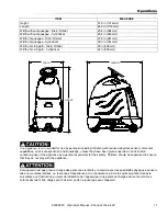
Page 11: ... ou mentales réduites ou le manque d expérience et de connaissance à moins qu ils aient été donnés la surveillance ou l instruction au sujet de l utilisation de l appareil par une personne chargée de leur sûreté Des enfants devraient être dirigés pour s assurer qu ils ne jouent pas avec l appareil ITEM MEASURE Height 51 8 in 1316mm Length 44 0 in 1118mm Width without squeegee Disk Orbital 23 4 in ...

Page 12: ...rushes motor side squeegees and lift actuator The two counter rotating brushes scrub the floor driven by a single motor The brush deck floats with constant brush pressure The side squeegees keep the cleaning solution within the brush deck width allowing the main squeegee to pick the solution up The function of the recovery system is to vacuum the soiled water back into the recovery tank The recove...

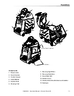
Page 13: ...rm 5 Solution Tank 6 Recovery Tank 7 Recovery Sight Dome 8 Recovery Drain Hose 9 Scrub Deck Skirt 10 Solution Cover 11 Solution Drain Hose Solution Level Indicator 12 Squeegee 86398220 Operators Manual Chariot 2 iScrub 20 Cylindrical Deluxe Disk Cylindrical 12 10 9 10 12 1 2 3 4 5 6 7 8 9 11 ...

Page 14: ...14 Operations Drive Controls 1 2 3 4 5 6 7 8 9 10 86398220 Operators Manual Chariot 2 iScrub 20 ...

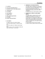
Page 15: ...hine at any time and apply parking brake To shut the machine power off push the Emergency Stop Switch this will also engage the parking brake and cause the machine to stop immediately To reset the machine rotate the switch clockwise 3 DIRECTIONAL CONTROL DRIVE RESET SWITCH This safety feature is designed to ensure safe engagement of propel drive Each time the machine power is turned on or each tim...

Page 16: ...ORN BUTTON The horn is activated by pressing the horn button 6 STEERING WHEEL The steering wheel turns the front wheel causing the machine to change direction 7 SPEED CONTROL Controls the maximum speed of the machine There are two settings slow and fast To change speed rotate the dial to either slow or fast position The slow position is to the left counterclock wise fast to the right top position ...

Page 17: ... vacuum only selection position B can be used to vacuum up any remaining water Return the unit to the charging station and charge the batteries NOTE Continuing usage may damage the batteries When the machine is left overnight with less than a full charge the display may initially indicate a full charge It will also indicate a full charge if the batteries are disconnected then reconnected After a f...

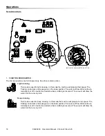
Page 18: ...matically shut off in neutral and restarts when scrubbing is resumed The vacuum will draw the water into the recovery tank Deep cleaning This mode is used for deep cleaning In this mode the machine will propel at a low speed The floating scrub deck and squeegee is in the down position The water will flow Water will auto matically shut off in neutral and restarts when scrubbing is resumed The vacuu...

Page 19: ... it back up The squeegee is set manually by connecting the two double scrub support cables In this mode the machine will propel at a slow speed The scrub deck will lower The solution will flow The brush and water will shut off when the machine is in neutral They will resume when propelling is resumed Light cleaning with chemical metering Chemical dilution rate to be set by chemical metering select...

Page 20: ...ns Scrub Controls Squeegee 1 Squeegee Latch 2 Squeegee Hose and Tube 3 Squeegee Wheels 3 4 Double Scrub Support Cable 5 Double Scrub Cable Hook 1 2 3 5 4 DISK ORBITAL 86398220 Operators Manual Chariot 2 iScrub 20 ...

Page 21: ...rrect height and angle to automatically obtain optimum suction 4 Double Scrub Support Cable The double scrub support cables retain the deck in the double scrub position 5 Double Scrub Cable Hook The double scrub cable hook is the connection point for the double scrub support cable Since the squeegee is raised and lowered by the scrub deck the double scrub position is set manually 86398220 Operator...

Page 22: ...solution tank with clean water leaving enough room for the required amount of cleaning solution The solution tank capacity filled to fill inlet is 10 gallons 38 liters The water must not be hot ter than 140 F 60 C to prevent damage to the tank 3 Measure the chemical into the solution tank Liquid chemicals should be added to the solution tank after filling with water Dry chemicals should be thoroug...

Page 23: ...lap the brush path and avoid transporting over previously cleaned areas To Begin Scrubbing When operating the machine around people pay close attention for unexpected movement Use extra caution around children Lorsque vous utilisez la machine en présence de gens portez une attention particulière aux mouve ments inattendus Soyez plus prudent surtout en présence d enfants Flammable liquids and or re...

Page 24: ... these cases it will be necessary to double scrub Connect the Double Scrub Cables to the squeegee Rotate the knob to the double scrub position To support the squeegee off the floor for double scrub pull the support cables down one side at a time and connect to the hook on the squeegee while lifting and tilting the squeegee upward To collect the solution and complete the Double Scrub operation rele...

Page 25: ...t dome and cover surface 4 Clean off the float shut off screen and inspect for free movement of float 5 Replace the drain cap and secure drain hose 6 If machine is to be stored tilt the recovery tank back and prop the console up partially opening each Solution Tank 1 Pull the solution drain hose from its mounting pocket Lower hose in direction of drain 2 Open the control console 3 Flush the soluti...

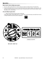
Page 26: ...r Run machine on the 4oz gal dilution rate to purge chemical through the system until the chemical bottle is empty Set dilution rate for next cleaning Chemical Metering Controls 1 CHEMICAL METERING SELECTION SWITCH OPTIONAL Three position switch controls dilution rates of 1 2 and 4 oz gal Chemical metering is activated from the main controlpanelwiththerotaryswitch positionsmarkedwith 86398220 Oper...

Page 27: ...27 Notes 86398220 Operators Manual Chariot 2 iScrub 20 ...

Page 28: ...solution tank Clean and inspect solution filter strainer Run vacuum motor to dry Clean brush or pad and check wear Clean squeegee blades and check wear Clean outside of tanks check for damage Store with console cover propped open Charge batteries if needed Empty and clean out debris bin Clean off top of batteries Check battery cells with hydrometer Wet cell only Inspect scrub deck skirt Clean solu...

Page 29: ...29 Maintenance Batteries 1 Cover Retainer Latch 2 Rear Cover 3 Battery Connector Machine 4 Batteries 5 Battery Tray 1 3 4 5 2 86398220 Operators Manual Chariot 2 iScrub 20 ...

Page 30: ...l below 25 specific gravity below 1 155 Keep all metallic objects off the top of the batteries as they may cause a short circuit Replace worn or damaged cables and terminals Check the electrolyte level in each battery cell before and after charging the batteries Never add acid to the batteries use distilled water Do not allow water level to fall below the battery plates Portions of plates exposed ...

Page 31: ...tection lorsque vous travaillez avec des batteries Charge batteries in a well ventilated area Chargez les batteries dans un endroit bien ventilé Battery Maintenance 1 When cleaning the batteries use a solution of baking soda and water Do not allow the cleaning fluid to enter the battery cells electrolyte will be neutralized 2 Maintain the proper electrolyte level in each battery cell If a cell sho...

Page 32: ...en when the battery electrolyte is any temperature other than 80 F 27 C the reading must be temperature corrected To find the corrected specific gravity reading when the temperature of the battery electrolyte is other than 80 F 27 C Add to the specific gravity reading 0 004 4 points for each 10 F 6 C above 80 27 C Subtract from the specific reading 0 004 4 points for each 10 F 6 C below 80 F 27 C ...

Page 33: ... batteries are fully charged 1 Stop the machine in a clean well ventilated area next to the charger 2 Turn OFF machine FOR SAFETY Before leaving or servicing machine stop on level surface turn off machine and remove key 3 Open rear cover to expose batteries unplug batteries from machine Batteries emit hydrogen gas Explosion or fire can result Keep sparks and open flame away Keep covers open when c...

Page 34: ...stop on level surface turn off machine and remove key 1 Open the console cover 2 Tilt the rear cover recovery tank back The rear cover recovery tank can also be removed for better access 3 If equipped with optional on board charger tilt charger mount to rear of machine 4 Disconnect battery pack from machine 5 Use the proper size open end wrench to discon nect main ground wire first and secure cabl...

Page 35: ...input power supply cord set is damaged replace with a cord that is appropriate for your region North America UL or CSA listed approved detachable cord at least 1 8m in length 6 feet 3 conductor 16AWG minimum and rated SJT termi nated in a grounding type IEC 60320 C14 plug rated 250V 13A minimum All other regions Safety approved detachable cord 3 conductor 1 5mm minimum rated appro priately for ind...

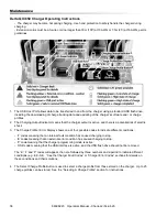
Page 36: ...ws one of four possible codes to indicate different conditions F codes meaning that an internal fault condition has caused charging to stop E codes meaning that an external error condition has caused charging to stop P code meaning that the charger programming mode is active USB code meaning that the USB interface is active and the USB flash drive should not be removed The E F and P codes will app...

Page 37: ...ld the button for 10 seconds to confirm your selection Process will time out and profile will remain unchanged if there is 15 seconds of inactivity a profile number is allowed to display three times or if AC power is cycled 4 Once desired charging profile is displayed press and hold button for 10 seconds see Figure 3 to confirm selection and exit Profile Selection Mode 5 Press the Select Charge Pr...

Page 38: ...egin the reprogramming process When complete the Fault Error USB Indicator will be solid green as shown Troubleshooting If the alarm indicator flashes amber note the error code and retry the update If there is no response to inserting the USB drive when the charger is being used off board check that AC power is available and connected If the charger is installed on board ensure that the charger ei...

Page 39: ...shing green light If you plan to download data from a large number of chargers having more free space on your USB flash drive is recommended If you want to update the software on only some of your chargers it is recommended that you use separate USB flash drives for updating and downloading charge tracking data Figure 5 Insert the USB flash drive to begin the charge data download process This step...

Page 40: ... squeegee in the up position turn key switch OFF 2 Disconnect vacuum hose from squeegee and squeeze the squeegee retaining latch 3 Pull squeegee assembly from the squeegee arm 4 Inspect or repair as necessary and reinstall To Replace or Rotate Squeegee Blades 1 With the squeegee in the up position turn key switch OFF FOR SAFETY Before leaving or servicing machine stop on level surface turn off mac...

Page 41: ...eegee Blades 1 With the squeegee in the up position turn key switch OFF FOR SAFETY Before leaving or servicing machine stop on level surface turn off machine and remove key 2 Remove the squeegee assembly from the machine 3 Unscrew two yellow thumb screws Remove bumper wheels and plastic end caps 4 Slide squeegee blade s out the end of the squeegee 5 Reverse procedure to install new blades Squeegee...

Page 42: ...rub Brush Motor SCRUB DECK ORBITAL 1 Scrub Deck Side 3 Scrub Deck Lift Actuator 2 Scrub Pad Motor 1 Scrub Deck Side 3 Scrub Deck Lift Actuator 2 Scrub Brush Motor 2 1 3 2 3 1 2 1 3 SCRUB DECK DISK SCRUB DECK CYLINDRICAL 86398220 Operators Manual Chariot 2 iScrub 20 ...

Page 43: ...um Green Hard Finished Floors Polypropylene is a general purpose scrub brush with stiff bristles Polypropylene works well for maintaining routed tile floors Nylon bristles are used in a variety of applications on coated or uncoated surfaces White Pads Polishing are used for dry polishing to achieve a high gloss appearance or surface washing on highly polished or burnished floors Red Pads Buffing a...

Page 44: ... assembly Turn clockwise until release lever plate locks into position 6 Check that release lever plate is completely closed and pad brush is securely attached NOTE Damage to driver or brush could occur if not securely attached Replacing or Installing Scrub Pad Orbital FOR SAFETY Before leaving or servicing the machine stop on level surface turn OFF machine and remove key 1 Turn machine power off ...

Page 45: ...re brushes are secure 5 Close side squeegee and latch securely Removal or Installation of Debris Bin Cylindrical NOTE On models with chemical metering system scrub deck needs to be lowered to remove debris bin 1 From right side of machine lift debris bin and sllde out 2 Re install in reverse order Brush Release 86398220 Operators Manual Chariot 2 iScrub 20 Debris Bin Slide out ...

Page 46: ...side orientation is determined from operators view 7 Remove brush pad 8 Remove driver 9 Remove three 3 screws securing brush motor to deck 10 Remove brush motor 11 Reverse steps to install To Replace Scrub Brush Motor Orbital With the scrub deck in the lowered position disconnect brush motor wiring connector from harness 1 Disconnect electrical connections 2 Remove squeegee 3 Remove front bumper 4...

Page 47: ... solenoid valve 3 Remove squeegee assembly 4 Remove front bumper 2 bolts 5 Remove four front bolts connecting deck lifting arms to front of machine 6 Remove actuator lifting pin and washers 7 Remove solenoid valve and cover 2 screws 8 Disconnect motor plug from harness 9 Slide deck out from under machine on right side orientation is determined from operators view 10 Remove metal cover over motor b...

Page 48: ...t actuator pins can be removed 2 Remove bumper screws 2 3 Remove front battery 4 Pull steering shaft 5 Disconnect actuator from wiring harness 6 From the underside of the machine remove lower lifting pin from actuator 7 Remove clevis pin from actuator upper bracket 8 Lift actuator upward and free from machine 9 Reverse steps to install 86398220 Operators Manual Chariot 2 iScrub 20 ...

Page 49: ... pressing the exposed button If a circuit breaker continues to trip the cause of the electrical overload should be found and corrected 1 5 Amp protects the brush deck lift actuator horn controller 18 Amp protects the vacuum motor 12 Amp protects the brush motor Disk Orbital 25 Amp protects the brush motor Cylindrical CIRCUIT BREAKERS 86398220 Operators Manual Chariot 2 iScrub 20 ...

Page 50: ...50 Maintenance Solution 1 Solution Strainer Coarse 2 Shut off Valve 3 Solenoid Valve 1 3 2 CYLINDRICAL 3 86398220 Operators Manual Chariot 2 iScrub 20 ...

Page 51: ... OFF FLOW VALVE Located below the solution tank on the right side If no flow check lever position Horizontal is no flow Up is maximum flow If clogged in the maximum position unscrew fittings inspect and clean if needed 3 SOLENOID VALVE The solenoid valve shuts off solution flow to scrub deck whenever scrubbing stops The solenoid valve is mounted on the front of the scrub deck on left side Shut off...

Page 52: ...their mounting plate locate and depress the lock tab and pull the connectors apart Replace the lower half of the connectors on to the support plate after the tank assembly has been removed 9 Remove the battery cable connection from the rear cross member 10 Close the console cover 11 Locate the solution solenoid valve on the left side of the scrub deck Remove two electrical wires from the valve The...

Page 53: ...hain cover plate off of the motor 5 Support the chassis on the tip pads so that the front wheel is 10 inches off the floor 6 Locate and remove two mounting nuts and remove the drive unit from below 7 To reinstall reverse the process 8 Note the small tab at the front of the drive unit frame should line up with the notch in the mating plate 86398220 Operators Manual Chariot 2 iScrub 20 ...

Page 54: ...54 Maintenance Vacuum Float Shutoff 1 Recovery Tank Float Shut off 2 Vacuum Motor 1 2 86398220 Operators Manual Chariot 2 iScrub 20 ...

Page 55: ...r Replace Vacuum Motor 1 Remove four 4 screws from top of control panel 2 Tip control panel back from console to expose vacuum motor wires 3 Disconnect electrical connector from the vacuum motor 4 Replace control panel attach with one 1 screw to secure in place 5 Open console 6 Remove three 3 screws that secure vacuum motor 7 Reverse steps to install NOTE If vacuum motor is not mounted as shown va...

Page 56: ...at holds each lead Remove the brushes 8 Install the new brushes and reinstall the band 9 Replace the gasket and cover set the drive wheel straight ahead set the steering wheel straight ahead and gently align the steering shaft coupling and slide onto the lower shaft 10 Slowly close the cover and make sure the shaft slides without binding Drive Chain Tension The drive chain should deflect about 1 4...

Page 57: ...erated while pushing the machine and may cause the controller to temporarily stop the machine 6 To re engage the brake push the lever as indi cated 7 Reinstall the access panel and reconnect the batteries Inclines When navigating an incline the machine may come to a stop Turn the machine off Wait 5 minutes and start the machine and proceed up the incline Overheating may occur if you do not wait th...

Page 58: ...he right hand stop to access the right side carbon brush 8 Replace the gasket and cover set the drive wheel straight ahead set the steering wheel straight ahead and gently align the steering shaft coupling and slide onto the lower shaft 9 Slowly close the cover and make sure the shaft slides without binding Drive Chain Tension The drive chain should deflect about 1 4 inch on either side of the loo...

Page 59: ...engage on a level surface Rotate lever firmly in direction of arrow Inclines When navigating an incline the machine may come to a stop Turn the machine off Wait 5 minutes and start the machine and proceed up the incline Overheating may occur if you do not wait the full 5 minutes Une surchauffe peut se produire si vous n attendez pas les 5 minutes complètes 86398220 Operators Manual Chariot 2 iScru...

Page 60: ...ts located in front of the rear wheels on the frame and a Tie down wrap point on the recovery tank Tie down devices must be of the proper type and strength The combined strength of all tie downs must be strong enough to lift two times the weight of the machine Tie downs must be positioned to prevent the machine from moving forward backward or either side to side Use all four corners of the machine...

Page 61: ...rength of all tie downs must be strong enough to lift two times the weight of the machine Tie downs must be positioned to prevent the machine from moving forward backward or either side to side Use all four corners of the machine with the tie downs running out opposite directions Tie downs must be attached to the trans porting vehicle securely 86398220 Operators Manual Chariot 2 iScrub 20 CONNECT ...

Page 62: ...ttle circuit or potentiometer Check wires and connections from and potentiometer resistance Drive Lever disengaged Engage drive Machine does not change speeds Faulty speed control circuit or switch Check wires connections Forward speed only Reverse speed only Faulty forward reverse circuit Check wires connections Poor or no water pickup Debris caught on squeegee Remove debris Worn squeegee blades ...

Page 63: ...olution strainer plugged Clean solution strainer Solution system plumbing obstructed Clear obstruction from plumbing Solution solenoid valve obstructed or stuck Solution solenoid valve obstructed or stuck Solution metering valve is closed Open metering valve Faulty solenoid Check solenoid valve Brush motor does not run or runs slowly Circuit breaker tripped Reset circuit beaker Low battery charge ...

Page 64: ...r service agent 4 The battery charge level has fallen below the battery Lockout Level and the controller is inhibiting scrub motor function Charge the battery 5 Not used 6 The controller is being inhibited from driving this may be because the battery charger is connected on board charger only Disconnect battery charger 7 A throttle fault is indicated Make sure that the throttle is in the rest posi...

Page 65: ...65 Notes ...

Page 66: ...EE FRONT 86000420 BRUSH POLYPROPYLENE 86000430 BRUSH NYLON 86283870 BRUSH NYLON POLISH 86326070 SQUEEGEE REAR 86369160 WHEEL 86328020 VACUUM HOSE 86223470 RING 86384090 BRUSH SET DRIVE MOTOR 86135310 BRUSH SET VACUUM MOTOR 86331980 BRUSH SET SCRUB MOTOR 86398220 Operators Manual Chariot 2 iScrub 20 ...

Page 67: ... Parts Orbital 86334700 DRAIN HOSE 86007970 STRAINER 86219690 KNOB 86326060 SQUEEGEE FRONT 86326070 SQUEEGEE REAR 86369160 WHEEL 86328020 VACUUM HOSE 86223470 RING 86384090 BRUSH SET DRIVE MOTOR 86135310 BRUSH SET VACUUM MOTOR 86399920 BRUSH SET ORBITAL SCRUB MOTOR ...

Page 68: ...CTOR ROLL STAR GRIP END PIECE LEFT SQUEEGEE BLADE REAR SQUEEGEE BLADE FRONT 86348190 NUT WHEEL 47623930 ROLLER BRUSH RED 47624090 ROLLER BRUSH WHITE 47624100 ROLLER BRUSH ORANGE 47624110 ROLLER BRUSH GREEN 47624120 ROLLER BRUSH BLACK 86328020 VACUUM HOSE 86369160 WHEEL 86223470 RING 86384090 BRUSH SET DRIVE MOTOR 86135310 BRUSH SET VACUUM MOTOR 86398220 Operators Manual Chariot 2 iScrub 20 ...

Page 69: ...69 86398220 Operators Manual Chariot 2 iScrub 20 Notes ...

Reviews: