Wilo SCPV Installation And Operating Instructions Manual Download Page 26

Installation and operating instructions  Wilo 

 SCPV pumps 

25 


until  required  for replacement  or refit on to the 
spindle  if  needed.  In  case  of  immediate  use, 
coating  of  rust  preventive  oil  is  not 
necessary.(See Annexure 2) 

9.4.6   Stuffing box bush


Check bore  of  stuffing  box bush  and  compare 
with  sleeve  diameter.    If  "clearance

  is 

excessive, the  bush  should be renewed. 


9.4.7   Shaft


Check  the  shaft  for  trueness.  Since  sleeves 
protect  shaft  and  very little  portion  is  exposed, 
no  wear  is  expected.  However  in  case  of 
aggressive  liquid,  the  exposed  portion  should 
be inspected for corrosion attack 


9.4.8   Mechanical seal


Ensure that the sliding face do not have any 
scratches or abnormal wear. Verify that the 
driving collar is well screwed on the shaft at  the 
right place . Check that no material block the 
spring action 


9.5   

Reassembling the pump


9.5.1   Reassembly of rotating element


If  rotating  element  has  been  completely 
dismantled,    the    correct    position    for    the 
impeller  must  be established  as  marked  on  the 
shaft  prior  to  dismantling.  Then  commence 
reassembly as under. 


Fit the Intermediate Shaft Sleeves. 


Fit  the  impeller  keys  in  the  keyway  of  the 

spindle. 


Fit  the  Impellers  along  with  Neck  rings  on 

the spindle in correct position. 

Note:


While  assembling  stainless  steel  component 
molybdenum-disulphide 

paste  should  be 

applied  to  prevent  galling  / seizure  and  also  to 
facilitate easy removal in future. 


9.5.2   Re-assembly of the pump


(Gland pack version pump)


Ensure that casing is clean, dry and free from 

foreign    matter.    Clean    casing    neck    ring 
seating  thoroughly  and  ensure  they  have  no 
burrs 


Carefully  insert  the  element  into the  bottom 

half  casing,  with  the  help  of  withdrawal  gear 
trolley / crane. 


Fix  water  throwers,  dust  covers  and  outer 

end  covers  to  bearing  housing  by  their 
setscrews. 


Cut  a  gasket  from  0.25  mm  thick  black  joint 

paper or similar gasket material and locate on 
split flange of bottom half casing. 


Position  the  top  half  casing  by  crane  /  chain 

pulley  block  with  respect  bottom  half  casing 
so   that   split   faces   match.   Use   withdrawal 
gear  trolley  /  crane  to  support  the  top  of 
casing. 


Fit  the  split  flange  studs.  Align  dowel  holes  and  fit 
dowel  pins  before  tightening  the  nuts.    The  nuts 
must  be  tightened  evenly  in  the  diagonally  opposite 
sequence. (Refer Figure: 9) 

9.5.3  Reassembly of pump


(Mechanical seal version)


Ensure   that   casing   is   clean,   dry   and   free   from 
foreign  matter.  Clean  casing  neck  ring  seating 
thoroughly and ensure they have no burrs 


Carefully   place  the  adjusting  ring  of  mechanical 

seal at its premarked position 


Place   the   grub   screw   at   its   position   on   the 
adjusting ring 


The  O-ring  may  be  oiled  to  reduce  friction  during 

installation  of  the  seal.  But  the  EP-  rubber  O-ring 
should  not  come  in  contact  with  oil  or  grease.  In 
this  casse  lubrication  with  glycrol  or  water  is 
recommended 


Never cover the sliding  faces with lubricants  , they 

should   be   assembled   completely   dry   clean   and 
dust free 


When  pressuring  staionary  seal  make sure that the 

pressure  distrubition  is  unifor.  The  O-ring  must  be 
fitted using water or glycerolonly 


Crowned   drive  pins  must  be  replaced   whenever 

the  seal  is  dismantled.  During  insertion  of  the 
stationary  seats, especially  those of special  carbon, 
care must be taken to exert pressure evenly 


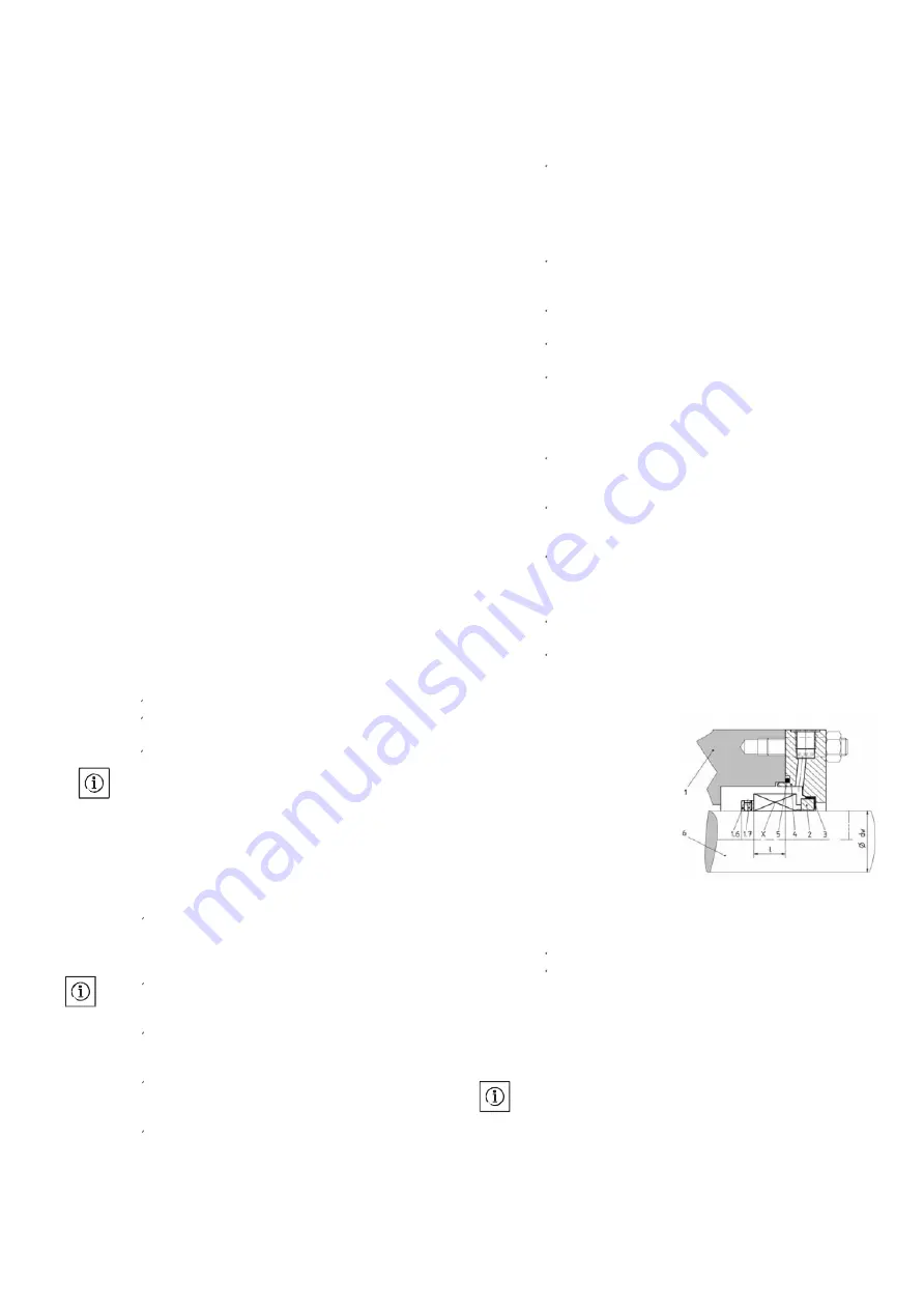
Now  check  the  distance  of  seal  as  shown  in  the 
figure and adjust its value as per values given table 


For    rest    parts    follow    the    above     explained 

procedure as per gland pack version pump 


Location of mechanical seal of shaft 


1)   Pump casing 
2)   Stationary seat 
3)   Stationary seat 
4)   Gland plate 
5)   O-ring 
6)   Shaft 
X.    Mechanical seal 
1.6 Abutment ring 
1.7 Abutment ring fixing screw 


9.5.4   Final Assembly


Refit and reconnect pump half coupling. 


Prime the pump and return it to service 

NOTE:


While  assembling    stainless    steel    component, 
molybdenum-disulphide    paste  should  be  applied  to 
prevent  galling  /  seizure  and  also  to  facilitate    easy 
removal in future. 


NOTE:


Change  the  gasket   each   time  when   the   pump  is 
opened. 

Summary of Contents for SCPV

Page 1: ...Wilo SC PV_ 201 310 10_ E0 3 Wilo SCPV pumps en Installationand operating instructions...

Page 2: ...l and maintain the pump shall be responsible for hassle free installation operation or maintenance of the product This document is prepared with at most care to ensure correct and accurate information...

Page 3: ...tion and operating instructions Wilo SCPV pumps 2 Fig 1 Pump Handling 3 1 Fig 2 Pump Foundation 7 2 1 Bare Pump HorizontalLifting bar Lifting ropes Motor Motor Stool Split case Pump Pump Stool Foundat...

Page 4: ...Installation and operating instructions Wilo SCPV pumps 3 Fig 3 Coupling assembly 7 2 3 Fig 4 Suction Layout 7 2 5 Fig 5 Suction Layout 7 2 5...

Page 5: ...Installation and operating instructions Wilo SCPV pumps 4 Fig 6 Discharge Layout 7 2 6 Fig 7 Discharge Layout 7 2 6...

Page 6: ...Installation and operating instructions Wilo SCPV pumps 5 Fig 8 Gland Packing Details 7 2 7 Fig 9 Bolt tighting sequence 9 5 2...

Page 7: ...ended use 9 5 Product information 10 5 1 Data plate 10 5 2 Type key 10 5 3 General description 10 5 4 Scope of delivery 11 5 5 Accessories 11 6 Description and function 11 6 1 Description of the produ...

Page 8: ...uries WARNING The user can suffer serious injuries Warning implies that serious injury to persons is probable if this information is disregarded CAUTION There is a risk of damaging the pump installati...

Page 9: ...e when the pump is supplied along with motor panels When motor panel is in end user s scope of supply it isadvised to go for CE approved motors panels Environmental safety Disposal of any unwanted scr...

Page 10: ...p on operation 3 3 2 Long term storage more than 3 month If the equipment will be subject to extended storage condition prior to installation then the manufacturer must be informed about storage durat...

Page 11: ...odel dependent Discharge nominal diameters DN 50 up to 400 Flange standard PN 16 25 ISO 7005 2 as needed Limit of fluid temperature min max Mechanical seal version C Gland packing version C 8 up to 12...

Page 12: ...ion for neck rings Tapings are provided in top half casing for taking water seal flushing connection to the stuffing box Tapings are also provided on top of casing for mounting air cock for venting Th...

Page 13: ...sher 2105 Non drive end shaft sleeve 2410 Gland packing 3001 Cowl Nut L H 2300 Lantern ring 3031 Sleeve nut L H 2070 Water Thrower 3032 Sleeve nut R H 3250 Coupling key For Mechanical Seal No Part des...

Page 14: ...d be taken to bar persons from standing beneath a suspended load Further more it is also prohibited to move suspended loads over exposed workplaces where people are present The fastening devices shoul...

Page 15: ...motor Avoid exposure of the pump to direct sunlight An appropriate solution to avoid frost must be implemented CAUTION Risk of material damage Ensure sufficient ventilation heating if the ambient tem...

Page 16: ...t mix in the proportion specified earlier for foundation bolt grouting should be used 7 2 3 Alignment of the pumps and its driving units When the sole plate is leveled and the satisfactory alignment i...

Page 17: ...xed relation to the diameter of the suction branch of the pump The size of the pipe must be such that friction losses are kept to a minimum For example a long suction pipe or one with numerous bends w...

Page 18: ...Mechanical seal CAUTION Damage to the pump Never start the pump without liquid inside otherwise the mechanical seal will be damaged instantaneously No real operation is required during the setup of t...

Page 19: ...ay become very hot depending on the operating state of the pump or system fluid temperature CAUTION Danger sealing system damage Any attempt to run the pump dry or partially full may result in seizure...

Page 20: ...k that all electrical checks on motor relay setting in panel etc have been carried out in accordance with the instructions of motor manufacturer Ensure that mechanical seal connection is provided as s...

Page 21: ...g the pump If the gland plate is too tight the packing stuff willbe immediately damage At the beginning of the operation the leak at the gland packing should be important It should reduce progressivel...

Page 22: ...in a fortnight and values compared with that of previous records Check that there is sufficient leakage from the gland packing to ensure proper cooling and lubrication If applicable For mechanical se...

Page 23: ...wearable components may require renewal Measurements should be taken and recorded of all wearable components at the first and every subsequent overhaul period Reference to these records will enable a...

Page 24: ...r neck will indicate the amount of diametrical clearance between the casing neck ring and the impeller neck 9 4 2 Shaft Sleeves The shaft sleeve should be examined to see if it is grooved or generally...

Page 25: ...must be smaller than the corner radius of the track located against the abutment The edge of the abutment must be reduced or chamfered a burred edge can tilt or distort a bearing track If after inspe...

Page 26: ...on split flange of bottom half casing Position the top half casing by crane chain pulley block with respect bottom half casing so that split faces match Use withdrawal gear trolley crane to support t...

Page 27: ...pump wear rings and their nuts For the pumps equipped with Gland packing include the gland plate and lubrication spacer For5 years of normal operation Take the same lot of part as for 3 years and add...

Page 28: ...Gland 1 15 Stud for gland 2 16 Bearing end cover Drive End 1 17 Bearing DriveEnd 1 18 Bearing housing DriveEnd 1 19 Thrust collar 1 20 Bearing end cover NonDrive End 1 21 Stud for bearing end cover 1...

Page 29: ...Plate 2 14 Stud for gland 2 15 Bearing end cover Drive End 1 16 Bearing Drive End 1 17 Bearing housing Drive End 1 18 Thrust collar 1 19 Bearing end cover Non Drive End 1 20 Stud for bearing end cover...

Page 30: ...r leaks into suction line Tighten pipe joints with solution 8 Air leaks into pump through stuffing boxes Ensure stuffing box sealing 9 Foot valve too small or leaking Replace I Attend 10 Foot valve pa...

Page 31: ...of Provide clean liquid for flushing shaft or shaft sleeve 41 Excessive thrust caused by mechanical failure Check pump operation and assembly inside pump or by failure of hydraulic balancing device i...

Page 32: ...eve N D E 2300 Lantern ring 2310 Gland 2410 Gland packing 2600 Ball bearing 2702 Baering bush 2752 Bearing end cover D E inner 2753 Bearing end cover D E outer 2761 Bearing housing D E 2831 Bearing bu...

Page 33: ...sleeve N D E 2111 Spacer sleeve 2420 Mechanical seal 2421 Gland Plate 2402 Stuffing box bush 2601 Bearing 2700 Baering bush 2752 Bearing end cover D E inner 2753 Bearing end cover D E outer 2761 Bear...

Page 34: ...ot B N A 18 SCPV 150 530 HA 6311 ZZ Finocot B N A 19 SCPV 200 310 HA 3380 A Finocot B Grease 20 SCPV 200 320 HA 3380 A Finocot B Grease 21 SCPV 200 370 HA 3380 A Finocot B Grease 22 SCPV 200 360 HB 33...

Page 35: ...95 13 SCPV 150 290 HA 16 3 230 81 14 SCPV 150 390 HA 17 5 3 275 95 15 SCPV 150 350 HA 17 5 3 275 95 16 SCPV 150 440 HA 17 5 3 275 95 17 SCPV 150 580 HA 20 3 330 114 18 SCPV 150 530 HA 20 3 330 114 19...

Page 36: ...and Remove gland packing as well as logging ring In case of Mechanical seal remove the nuts of seal gland plate Remove all split flange nuts and the two dowel pins Withdraw the casing top by sliding o...

Page 37: ..._ _ _ _ _ _ _ _ _ _ _ _ _ _ _ __ _ _ _ _ _ _ _ _ _ _ _ _ _ _ _ _ _ _ _ __ _ _ _ _ __ Mather and Platt pumps Ltd Part of Wilo SE Germany Mumbai Pune Road Chinchwad Pune 411 019 Maharashtra India Tel 91...

Reviews: