W
il
o
S
C
P
V
_
20
1
31
0
10
E
3
Wilo
–
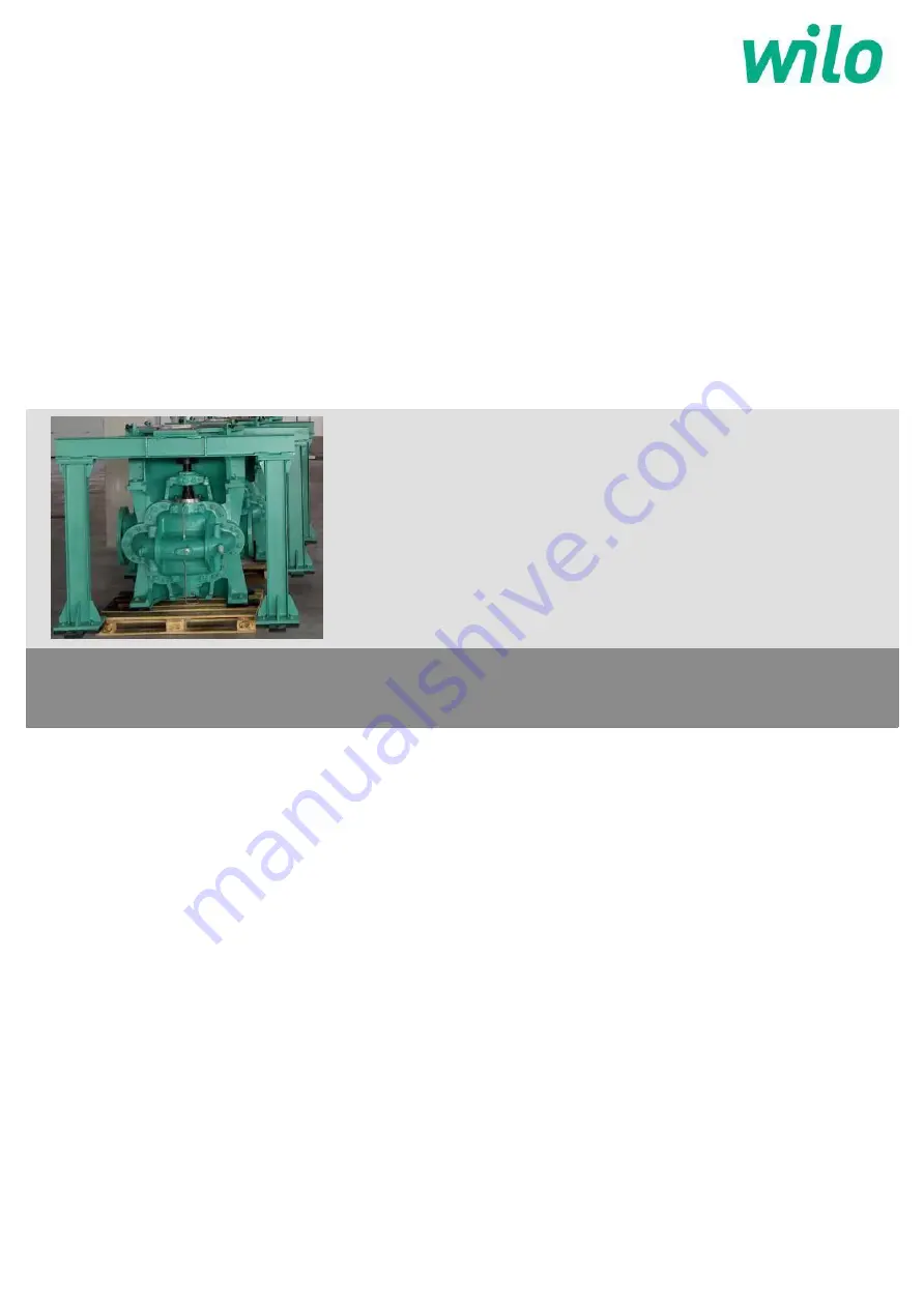
SCPV pumps
en
Installation and operating instructions
Page 1: ...Wilo SC PV_ 201 310 10_ E0 3 Wilo SCPV pumps en Installationand operating instructions...
Page 2: ...l and maintain the pump shall be responsible for hassle free installation operation or maintenance of the product This document is prepared with at most care to ensure correct and accurate information...
Page 3: ...tion and operating instructions Wilo SCPV pumps 2 Fig 1 Pump Handling 3 1 Fig 2 Pump Foundation 7 2 1 Bare Pump HorizontalLifting bar Lifting ropes Motor Motor Stool Split case Pump Pump Stool Foundat...
Page 4: ...Installation and operating instructions Wilo SCPV pumps 3 Fig 3 Coupling assembly 7 2 3 Fig 4 Suction Layout 7 2 5 Fig 5 Suction Layout 7 2 5...
Page 5: ...Installation and operating instructions Wilo SCPV pumps 4 Fig 6 Discharge Layout 7 2 6 Fig 7 Discharge Layout 7 2 6...
Page 6: ...Installation and operating instructions Wilo SCPV pumps 5 Fig 8 Gland Packing Details 7 2 7 Fig 9 Bolt tighting sequence 9 5 2...
Page 7: ...ended use 9 5 Product information 10 5 1 Data plate 10 5 2 Type key 10 5 3 General description 10 5 4 Scope of delivery 11 5 5 Accessories 11 6 Description and function 11 6 1 Description of the produ...
Page 8: ...uries WARNING The user can suffer serious injuries Warning implies that serious injury to persons is probable if this information is disregarded CAUTION There is a risk of damaging the pump installati...
Page 9: ...e when the pump is supplied along with motor panels When motor panel is in end user s scope of supply it isadvised to go for CE approved motors panels Environmental safety Disposal of any unwanted scr...
Page 10: ...p on operation 3 3 2 Long term storage more than 3 month If the equipment will be subject to extended storage condition prior to installation then the manufacturer must be informed about storage durat...
Page 11: ...odel dependent Discharge nominal diameters DN 50 up to 400 Flange standard PN 16 25 ISO 7005 2 as needed Limit of fluid temperature min max Mechanical seal version C Gland packing version C 8 up to 12...
Page 12: ...ion for neck rings Tapings are provided in top half casing for taking water seal flushing connection to the stuffing box Tapings are also provided on top of casing for mounting air cock for venting Th...
Page 13: ...sher 2105 Non drive end shaft sleeve 2410 Gland packing 3001 Cowl Nut L H 2300 Lantern ring 3031 Sleeve nut L H 2070 Water Thrower 3032 Sleeve nut R H 3250 Coupling key For Mechanical Seal No Part des...
Page 14: ...d be taken to bar persons from standing beneath a suspended load Further more it is also prohibited to move suspended loads over exposed workplaces where people are present The fastening devices shoul...
Page 15: ...motor Avoid exposure of the pump to direct sunlight An appropriate solution to avoid frost must be implemented CAUTION Risk of material damage Ensure sufficient ventilation heating if the ambient tem...
Page 16: ...t mix in the proportion specified earlier for foundation bolt grouting should be used 7 2 3 Alignment of the pumps and its driving units When the sole plate is leveled and the satisfactory alignment i...
Page 17: ...xed relation to the diameter of the suction branch of the pump The size of the pipe must be such that friction losses are kept to a minimum For example a long suction pipe or one with numerous bends w...
Page 18: ...Mechanical seal CAUTION Damage to the pump Never start the pump without liquid inside otherwise the mechanical seal will be damaged instantaneously No real operation is required during the setup of t...
Page 19: ...ay become very hot depending on the operating state of the pump or system fluid temperature CAUTION Danger sealing system damage Any attempt to run the pump dry or partially full may result in seizure...
Page 20: ...k that all electrical checks on motor relay setting in panel etc have been carried out in accordance with the instructions of motor manufacturer Ensure that mechanical seal connection is provided as s...
Page 21: ...g the pump If the gland plate is too tight the packing stuff willbe immediately damage At the beginning of the operation the leak at the gland packing should be important It should reduce progressivel...
Page 22: ...in a fortnight and values compared with that of previous records Check that there is sufficient leakage from the gland packing to ensure proper cooling and lubrication If applicable For mechanical se...
Page 23: ...wearable components may require renewal Measurements should be taken and recorded of all wearable components at the first and every subsequent overhaul period Reference to these records will enable a...
Page 24: ...r neck will indicate the amount of diametrical clearance between the casing neck ring and the impeller neck 9 4 2 Shaft Sleeves The shaft sleeve should be examined to see if it is grooved or generally...
Page 25: ...must be smaller than the corner radius of the track located against the abutment The edge of the abutment must be reduced or chamfered a burred edge can tilt or distort a bearing track If after inspe...
Page 26: ...on split flange of bottom half casing Position the top half casing by crane chain pulley block with respect bottom half casing so that split faces match Use withdrawal gear trolley crane to support t...
Page 27: ...pump wear rings and their nuts For the pumps equipped with Gland packing include the gland plate and lubrication spacer For5 years of normal operation Take the same lot of part as for 3 years and add...
Page 28: ...Gland 1 15 Stud for gland 2 16 Bearing end cover Drive End 1 17 Bearing DriveEnd 1 18 Bearing housing DriveEnd 1 19 Thrust collar 1 20 Bearing end cover NonDrive End 1 21 Stud for bearing end cover 1...
Page 29: ...Plate 2 14 Stud for gland 2 15 Bearing end cover Drive End 1 16 Bearing Drive End 1 17 Bearing housing Drive End 1 18 Thrust collar 1 19 Bearing end cover Non Drive End 1 20 Stud for bearing end cover...
Page 30: ...r leaks into suction line Tighten pipe joints with solution 8 Air leaks into pump through stuffing boxes Ensure stuffing box sealing 9 Foot valve too small or leaking Replace I Attend 10 Foot valve pa...
Page 31: ...of Provide clean liquid for flushing shaft or shaft sleeve 41 Excessive thrust caused by mechanical failure Check pump operation and assembly inside pump or by failure of hydraulic balancing device i...
Page 32: ...eve N D E 2300 Lantern ring 2310 Gland 2410 Gland packing 2600 Ball bearing 2702 Baering bush 2752 Bearing end cover D E inner 2753 Bearing end cover D E outer 2761 Bearing housing D E 2831 Bearing bu...
Page 33: ...sleeve N D E 2111 Spacer sleeve 2420 Mechanical seal 2421 Gland Plate 2402 Stuffing box bush 2601 Bearing 2700 Baering bush 2752 Bearing end cover D E inner 2753 Bearing end cover D E outer 2761 Bear...
Page 34: ...ot B N A 18 SCPV 150 530 HA 6311 ZZ Finocot B N A 19 SCPV 200 310 HA 3380 A Finocot B Grease 20 SCPV 200 320 HA 3380 A Finocot B Grease 21 SCPV 200 370 HA 3380 A Finocot B Grease 22 SCPV 200 360 HB 33...
Page 35: ...95 13 SCPV 150 290 HA 16 3 230 81 14 SCPV 150 390 HA 17 5 3 275 95 15 SCPV 150 350 HA 17 5 3 275 95 16 SCPV 150 440 HA 17 5 3 275 95 17 SCPV 150 580 HA 20 3 330 114 18 SCPV 150 530 HA 20 3 330 114 19...
Page 36: ...and Remove gland packing as well as logging ring In case of Mechanical seal remove the nuts of seal gland plate Remove all split flange nuts and the two dowel pins Withdraw the casing top by sliding o...
Page 37: ..._ _ _ _ _ _ _ _ _ _ _ _ _ _ _ __ _ _ _ _ _ _ _ _ _ _ _ _ _ _ _ _ _ _ _ __ _ _ _ _ __ Mather and Platt pumps Ltd Part of Wilo SE Germany Mumbai Pune Road Chinchwad Pune 411 019 Maharashtra India Tel 91...