English
Installation and operating instructions Wilo-DrainLift XXL
9
6 Description and function
6.1 Description of the unit
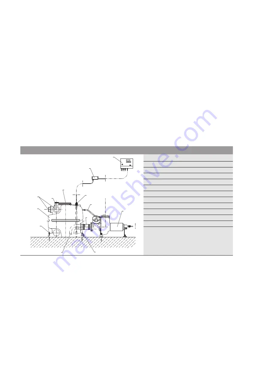
The DrainLift XXL sewage lifting unit (Fig. 1) is a pre-assembled, fully submersible sewage
lifting unit (flooding height: 2 mwc, flooding time: 7 days) with a gas and watertight col-
lection tank and buoyancy safeguards.
It is equipped with three-phase current pumps (3~400 V). The integrated level sensor
(Fig. 1, Pos. 3) registers the level in the tank and passes this value on to the switchgear,
which automatically switches the pumps on or off. The switchgear is equipped with a main
switch, integrated motor protection and automatic/hand/acknowledgement switch.
A detailed description of the functions can be taken from the operating instructions for the
switchgear.
Inlets can be connected to three sides of the DN 100/DN 150 combination socket. Sockets
on the top of the tank allow the pipe connection of a DN 50 inlet and DN 70 vent (see sec-
tion “Connecting the pipes”). An inspection opening enables easy maintenance of the unit.
Attachment slots are provided on both face sides of the collection reservoirs in order to
anchor the unit to the floor by means of the supplied fastening elements so that they are
anti-buoyant and cannot twist. The double-pump system is equipped with a base-load
pump and peak-load pump. The pumps are positioned horizontally in front of the tank and
suck the sewage out of the tank through the suction pipes. The suction pipes end in the
tank with a 90° elbow facing the base of the tank. This prevents deposits on the base to a
great extent. Likewise, a lower residual water volume and a higher switching volume is
achieved in this way.
6.2 Function
The discharged sewage is collected in the collection tank of the lifting unit. This is done via
sewage inlet pipes which can be connected to the existing pipe sockets as desired.
The DrainLift XXL sewage lifting unit is delivered with switchgear, Zener barrier (accesso-
ries kit) and pre-assembled level sensor.
The water level in the tank is registered by means of the integrated level sensor. If the
water level rises up to the set activation point, one of the pumps installed in front of the
tank(s) is switched on and the collected sewage automatically pumped into the connected
external sewage line.
The second pump is additionally activated if the water level continues to rise after the acti-
vation of the base-load pump. When the high level is reached, an optical signal is issued,
the alarm signal contact is actuated and there is a forced switch-on of all pumps. In order
for both pumps to be loaded evenly, pump cycling occurs after each pump cycle.
If one of the pumps fails, the other pump takes over the entire pumping work. The pump(s)
are deactivated once the deactivation level is reached.
Fig. 1: Description of the unit
1
Pump
2
Tank
3
Level switch with level sensor
4
Zener barrier
5
Switchgear
6
Suction pipe
7
DN 100/DN 150 inlet connecting piece
8
Emergency drain connection, DN 50
9
Ventilation connection
10
Inspection opening
11
Pump ventilation line
12
Suction line (slide valve, optional)
13
Buoyancy safeguards
1
2
3
4
5
7
6
8
12
11
9
10
13
0
I


