English
English
12
13
williamsjettenders.com
williamsjettenders.com
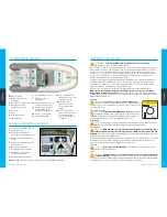
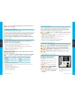
Lifting the Sportjet
CAUTION.
Damage to the tender may result if
the following procedure is not adopted.
Tilt helm down before attempting to lift the Sportjet
when using standard Williams-supplied lifting
strops. Lifting strops are available as an
optional accessory. Ensure hooks are
attached correctly before lifting.
WARNING.
Risk of injury or
death.
When Williams lifting
strops are used please adhere
to the Safe Working Load
values as follows:
Sportjet 460:
750 kg max
Sportjet 520:
750 kg max
Fuel System Check
WARNING.
Pressurised fuel system
. Inspect system for leaks at scheduled service
intervals. All elements of the fuel system function under pressure. The system remains
pressurised after engine is switched off. Extreme care must be taken when removing quick
connectors during filter change. Wear eye protection. No naked flames.
Routine Maintenance
To ensure long service life and to maintain the tender in a safe and reliable condition
please follow these routine maintenance instructions. Williams cannot accept any
responsibility for damage or injury resulting from incorrect maintenance or improper
adjustment carried out by the owner.
1
Wash tender regularly with fresh water to remove salt deposits.
2
Check engine oil level. When topping up, do not use synthetic oil; follow engine
manufacturer’s recommendations.
Engine must be at running temperature when
checking oil level.
3
Check coolant level.
4
Flush open loop cooling system.
5
Apply a good quality marine grease containing Teflon (e.g. Quicksilver 101) to all control
cables both under the helm and at the pump.
6
Check bilges for water ingress, oil or fuel contamination and clean if necessary.
7
Lightly grease the extending running light pole base using white grease or similar.
8
Check condition of all anodes.
9
Loss of tube pressure over 24 hours is not unusual. Temperature and atmospheric pressure
will affect tube pressures. Check pressures regularly.
10
For boats used in tropical environments, the frequency of the routine maintenance should
be increased accordingly.
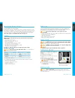
Fuse Identification
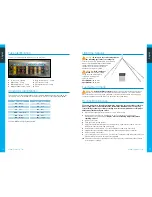
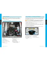
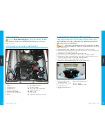
Fuses are located within the engine bay on the port side.
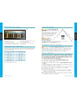
Conductor Identification
This chart sets out the corresponding colour to all cable printed abbreviations found on the
craft. Please refer to the Williams Technical Resource CD for the complete wiring diagram.
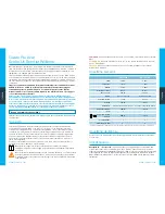
Code
Colour
Code
Colour
BK
Black
VT
Violet
GN
Green
RD
Red
PK
Pink
GY
Grey
LTGN
Light green
BE
Blue
BN
Brown
WE
White
OE
Orange
YW
Yellow
Example: GN/YW will signify Green/Yellow
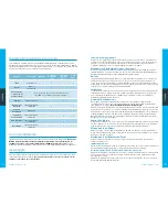
1
12 volt outlet: 20 amp
2
Bilge pump: 7.5 amp
3
Bilge pump switch: 7.5 amp
4
Navigation light switch: 5 amp
5
Bilge blower switch: 7.5 amp
6
VHF (option): 5 amp
7
Chartplotter (option): 5 amp
8
Spare
6
2
7
1
8
4
3
5


