Wieland
podis
system
Manual V 1.03 / ref. no. 00.000.0059.0 / 28.03.2001
6.1.6
Maintenance and service
If measuring or testing procedures are required on the
active device, the definitions and instructions for
implementation of the accident prevention regulation
VBG 4.0 should be observed. A suitable electronic tool
should be used.
Repairs to controller components may only be carried out
by authorised Wieland workshops. Unauthorised opening
and improper operation or repairs can lead to personal
injury or damage to the device.
Before opening a device, the connection to the power
supply system should always be isolated (withdraw the
mains plug or open the isolating switch).
Motor starters may never be installed or removed under
load. Bus couplers may only be changed when the power
is disconnected. Dismantling and installation should be
carried out according to the mechanical guidelines.
6.2 Switching
on
The system is activated by switching on
1. the auxiliary supply for the electronics and
2. the main supply for the load (400 V).
The connected motor control units are only then ready for
parameterisation or signal exchange with the DP master.
For information on switching on or starting up the
individual motor starters, please refer to the section
”Start-up and operation”.
6.3
Integration of the motor control units into
the automation system
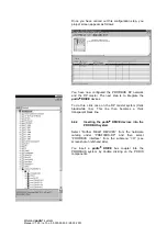
The PROFIBUS configuration tools require device-
specific information to enable the master and the PLC
system to exchange data with the slave. This information
is stored in the so-called master device file (GSD file) and
can be read by the configuration tool.
A GSD file is used for the formal description of a
PROFIBUS DP slave. In addition, it contains references
to graphics files (bitmaps) for the symbolic representation
of the DP slave in normal and diagnostics modes.


