


InstallatIon · Manual
Installation in pools with adhesive/foil coating
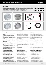
Orient the installation housing on the front cover (water side) according
to the marking and fix it in place. Correct orientation (in accordance
with drawing
3.2.
) of the installation housing on the boarded panel is
essential for later installation of the spotlight. If necessary, seal the outside
connection with silicone, for example, to keep dirt from penetrating inside
the installation housing. Fasten plastic end piece to the rear cover.
3.1.
Check installation housing, cable protection tube with clamps and plastic
end piece for firm hold.
After cementing in the installation housing and removing the cover, apply
adhesive/foil coating up to the inside edge of the installation housing.
attention:
The 2 fastening screw holes must be kept free for later
mounting of the spotlight. It may be necessary to pretreat the adhesive
flange for improved adhesion. This can be taken from the instructions for
the material used.
3.5.
Installation in pools with fitted foil or thin-
walled pools (pressure flange)
Orient the installation housing on the front cover (water side) according
to the marking and fix it in place. Correct orientation (in accordance
with drawing
3.2.
) of the installation housing on the boarded panel is
essential for later installation of the spotlight. If necessary, seal the outside
connection with silicone, for example, to keep dirt from penetrating inside
the installation housing. Fasten plastic end piece to the rear cover
3.1.
Check installation housing, cable protection tube with clamps and plastic
end piece for firm hold.
After cementing in the installation housing and removing the cover, insert
foil and open corresponding cutouts on the installation housing (eight 4.5
mm holes for screws on TK 182 and one 170 mm hole for spotlight).
3.7.
Evenly apply 8 screws to installation housing, seal, foil, seal, pressure
flange, avoiding folds in the foil, and tighten crosswise to 2,6 Nm.
3.6.
Montage dans les bassins avec revêtement
collé/liner
Aligner et fixer le boîtier d‘encastrement avec le revêtement collé sur le coffra-
ge avant (côté eau) en suivant le marquage. Il faut impérativement respecter
le bon alignement (suivant le schéma
3.2.
) du boîtier d‘encastrement sur la
paroi du coffrage pour y monter ultérieurement le projecteur. Le cas échéant,
étanchéifier l‘embase extérieure, par exemple avec du silicone, afin d‘éviter
que des salissures n‘entrent dans le boîtier d‘encastrement. Fixer l‘embout
d‘extrémité en plastique au coffrage postérieur.
3.1.
Vérifier la bonne fixation du boîtier d‘encastrement, de la gaine de protection
du câble avec colliers et de l‘embout d‘extrémité en plastique.
Après avoir bétonné le bassin puis retiré le coffrage, poser le revêtement collé/
liner jusqu‘au bord intérieur du boîtier d‘encastrement.
attention:
Les 2 trous filetés de fixation doivent être laissés libres pour
y monter plus tard le projecteur. Le cas échéant, le flasque de collage devra
être prétraité afin d‘améliorer l‘adhésion. Vous trouverez ces informations
dans la notice d‘utilisation du matériau utilisé. 3.5.
Montage dans les bassins avec revêtement in-
térieur ou à parois minces (flasque de pression)
Aligner et fixer le boîtier d‘encastrement sur le coffrage avant (côté eau) en
suivant le marquage. Il faut impérativement respecter le bon alignement
(suivant le schéma
3.2.
) du boîtier d‘encastrement sur la paroi du coffrage
pour y monter ultérieurement le projecteur. Le cas échéant, étanchéifier
l‘embase extérieure, par exemple avec du silicone afin d‘éviter que des
salissures n‘entrent dans le boîtier d‘encastrement. Fixer l‘embout d‘extrémité
en plastique au coffrage postérieur.
3.1.
Vérifier la bonne fixation du boîtier d‘encastrement, de la gaine de protection
du câble avec colliers et de l‘embout d‘extrémité en plastique.
Après avoir bétonné le bassin puis retiré le coffrage, mettre le revêtement en
place et réaliser une ouverture au niveau du boîtier d‘encastrement
(8 trous de diamètre 4,5 mm sur TK 182 et 1 trou de diamètre 170 mm pour
le projecteur).
3.7.
Positionner régulièremeent le boîtier d‘encastrement, le joint, le revêtement,
le flasque de pression, les 8 vis, éviter les plis dans le revêtement et serrer en
croix à 2,6 Nm.
3.6.
WIBRE Elektrogeräte Edmund Breuninger GmbH & Co. KG · Liebigstrasse 9 · 74211 Leingarten/Germany
Telefon: +49 (0) 7131 9053-0 · Telefax: +49 (0) 7131 9053-19 · E-Mail: [email protected]
3
/6
Montage in Becken mit Klebe-/Folienanstrich
Einbaugehäuse mit Klebeflansch an der vorderen Verschalung
(Wasserseite) nach Markierung ausrichten und fixieren. Die richtige
Ausrichtung (laut Zeichung
3.2.
) des Einbaugehäuses an der Schal-
wand ist für den späteren Einbau des Scheinwerfer unbedingt zu
beachten. Gegebenenfalls äußeren Bund z.B. mit Silikon abdichten
um das Eindringen von Schmutz ins Innere des Einbaugehäuses zu
vermeiden. Kunststoffabschlussstück an der hinteren Verschalung
fixieren.
3.1.
Einbaugehäuse, Kabelschutzrohr mit Schellen und Kunststoffab-
schlussstück auf festen Halt prüfen.
Nach dem Betonieren und Entfernen der Verschalung Klebe-/Folien-
anstrich bis Innenkante des Einbaugehäuses auftragen.
achtung:
Die 2 Befestigungsschraublöcher zu späteren
Scheinwerfermontage müssen freigehalten werden. Gegebenenfalls
muss der Klebeflansch zur Haftverbesserung vorbehandelt werden.
Dies ist der Gebrauchsanleitung des verwendeten Materials zu
entnehmen.
3.5.
Montage in Becken mit eingelegter Folie oder
dünnwandigen Becken (Druckflansch)
Einbaugehäuse an vorderen Verschalung (Wasserseite) nach
Markierung ausrichten und fixieren. Die richtige Ausrichtung (laut
Zeichnung
3.2.
) des Einbaugehäuses an der Schalwand ist für
den späteren Einbau des Scheinwerfer unbedingt zu beachten.
Gegebenenfalls äußeren Bund z.B. mit Silikon abdichten um das Ein-
dringen von Schmutz in Innere des Einbaugehäuses zu vermeiden.
Kunststoffabschlussstück an der hinteren Verschalung fixieren.
3.1.
Einbaugehäuse, Kabelschutzrohr mit Schellen und Kunststoffab-
schlussstück auf festen Halt prüfen.
Nach dem Betonieren und Entfernen der Verschalung Folie einlegen
und entsprechend am Einbaugehäuse aussparen (8 Löcher 4,5 mm
für Schrauben auf TK 182 und 1 Loch ø 170 mm für Scheinwerfer).
3.7.
Einbaugehäuse, Dichtung, Folie, Dichtung, Druckflansch, 8 Schrau-
ben gleichmäßig auflegen, Falten in der Folie vermeiden und mit 2,6
Nm kreuzweise anziehen.
3.6.
Netzteil
Power supply
Alimentation
196
89
500 mm
3.8
Mörtel
mortar
mortier
Fliesen
tiles
carreaux
max 40 m
5.0670.09.45, 5.0670.09.52
prim
230 V
RGBX
max 40 m
5.0670.04.72
prim
230 V
1
2
3
4
max 40 m
5.0670.02.72
prim
230 V
1
2
3.8
3.10
3.9
3.9
3.9


