2
Safety instructions
GENERAL INSTRUCTIONS
Please keep this instruction sheet for future reference.
When assembled and installed according to this
installation manual, the products will meet all security
aspects of the European standards EN1176
Do not alter the intended set-up in any way, as this
may cause the related certificates to become invalid.
Other than the recommended items, do not attach
any extra objects to the equipment, such as ropes
or chains. Only use the equipment or accessories as
intended. To avoid dangerous combinations, do not
combine products from other manufacturers with your
White Rhino construction.
White Rhino products are fit for outdoor commercial
playgrounds.
White Rhino products are suitable for individual users
weighing up to 70 kg.
The use of the items is allowed only under continuous
supervision by an adult. Risk of falling!
Equipment shall be constructed so that any openings
do not create entrapment of head, fingers, or clothing
as described in EN1176. To prevent finger entrapment,
openings shall not be less than 25 mm in diameter
unless the opening is smaller than 8 mm in diameter.
IMPACT AREA AND SAFETY SURFACE
When mounting or assembling the White Rhino
constructions, attention should be given to the
minimum required distance between the construction
and eventual obstacles (impact area). Dimension of
the impact area depends on the free height of fall. The
shape and size of the impact area and the falling space
of your White Rhino product can be found below in
this document.
The free space of the equipment is the space a
user is likely to be in during any forced movement
that may occur. With the exception of parts of the
equipment that are intended to bear or contain the
user or help the user to keep balance, the free space
of the equipment shall be free of obstacles (e.g. tree
branches, ropes, cross beams,…)
A White Rhino playground can be any combination of
the different White Rhino constructions. The impact
areas of two different pieces of equipment may
overlap, but there shall be no overlapping of free
spaces or of free space and falling space.
The safety surface underneath the White Rhino
construction must be flat, and be covered in a suitable
way (eg. rubber tiles, bark, wood chips) and meet
the requirements of EN 1176-1:2017. The product
must not be placed on asphalt, concrete or any other
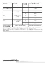
hard surface. Examples of commonly used impact
attenuating surfaces and their corresponding free
height of fall (as proposed in EN 1176-1:2017) can be
found in the table below.
Impact attenuating surfaces should be adequately
maintained and checked regularly according to
standard EN 1177. The impact attenuating properties
of the filing material can change over time due to
various circumstances like heavy use, degradation,
vandalism,… When using an impact attenuating
surface specified in the table below, no further testing
according to standard EN1177 is needed.
CONSTRUCTION
First check the contents of the boxes for part
quantities and damage. Always use the prescribed bolt
and nut connections.
No spare parts are provided with the device. In case
of a damage, spare parts can be obtained from the
manufacturer.
Connections shall be safeguarded so that they cannot
be undone without tools.
When using anchorage that is placed in concrete, the
concrete should be poured and shaped according to
the instructions found further in this manual. The
indicator of the ground surface level should be the
base level mark found on the anchor.
TOOLS AND CONNECTIONS
All sunken-head and flangehead screws delivered
with the White Rhino kits are self-drilling, drilling of
pilot-holes is not required. Although when using dry
or hard wood, we do recommend pre-drilling wood to
be screwed to prevent it from splitting. Always drill at
least 15 mm less deep than the length of the screw.
Pre-drill flangehead screws with a diameter of 8 mm
with a 5 mm wood bore bit.
Drive sunken-head screws with a correctly fitting
screw-bit in the wood until the head of the screw is
level with the surface of the wood. Avoid driving the
screws too deep into the wood as this will cause the
wood to split and splinters may appear.
Flangehead screws, bolts and nuts cannot be driven
completely into the wood. To prevent the protruding
parts of the screws and bolts to cause injuries, they
must always be protected with a boltcover. Place
the base part of the boltcover below the bolt or nut,
together with a washer and tighten. Make sure that
bolts and screws are fixed tight, before you close the
boltcover-caps.
WORK SAFELY
Wear work clothing and suitable protective equipment
(safety goggles, a dust mask and gloves) when
assembling your White Rhino playground equipment,
especially when sawing or drilling.
Sand all wood lightly, to avoid splinters and to remove
rough spots. Round off the corners on cut sides with
sandpaper or a file to get at least a 3mm radius on all
edges.
While assembling your White Rhino playground
equipment keep children away from the area and
make sure that they do not play on the equipment
until it is finished.
Follow the instructions for use of the tool you are
using.
At least two adults are needed to assemble the White
Rhino playground constructions.
GUARANTEE
Anyone buying a White Rhino product benefits from a
guarantee.
This guarantee can only be invoked if all the following
conditions have been met:
- the product displays a defect caused by faults in the
material or manufacture;
Summary of Contents for 009.006.001.001
Page 23: ......
Page 30: ......
Page 31: ...31 S1 S2 S3 S4 S5...
Page 32: ...32 x4 x4 A A ref 1 ref 3 ref 5 1 3 x2 B7 x2 B6 S1...
Page 33: ...33 3 3 16 A 2 A 2 2 3 ref 3 ref 6 ref 8 x12 C1 x48...
Page 34: ...34 x4 x4 ref 1 ref 3 ref 5 x2 B3 x2 B1 1 3 A A S2...
Page 35: ...35 950 mm 770 mm A 2 16 x2 x4 x2 3 3 ref 4 x36 x12 C1 ref 3 ref 6 ref 8 2 3...
Page 36: ...36 S3 1 1 ref 5 ref 6 ref 7 x16 x1 B3 x1 B2 x4 C1 A 2 16 C...
Page 37: ...37 S4 ref 5 ref 6 ref 7 x24 x2 B3 x6 C1 1 1 C...
Page 38: ...38 S5 ref 5 ref 6 ref 7 1 1 x2 B1 x4 C1 B C C B x16...
Page 39: ...39 S1 1 16...
Page 40: ...40 x1 B7 x2 x2 ref 2 3 16 x4 x2 300 mm x2 A3 x2 x2 x2 x2 x6 ref 1 ref 2 2 16...
Page 41: ...41 x1 A4 x1 x1 x1 x1 x3 ref 1 ref 2 5 16 x1 A1 x1 x1 x1 x1 x3 300 mm ref 1 ref 2 4 16...
Page 42: ...42 x1 C4 x2 7 16 x1 B6 x1 x1 x1 x1 x3 ref 1 ref 2 6 16...
Page 44: ...44 S3 S4 x6 ref 1 ref 2 11 16 x2 x1 C4 x2 10 16...
Page 45: ...45 x4 x8 x4 x4 ref 4 13 16 S5 x8 x6 ref 1 12 16 x1 B5...
Page 46: ...46 x2 A1 x4 x4 x4 ref 4 15 16 x4 300 mm x2 B4 x4 x8 14 16...
Page 47: ...47 min 25 mm max 45 mm x20 C2 x80 ref 6 16 16...
Page 48: ...48...
Page 49: ...36 0 mm x4 x4...
Page 51: ...51 x1 x1 2 2 x1 A B x1 3 15 20 mm 5 10 mm 6 ref 1 1 2...
Page 52: ...52 x1 x1 x1 2 3 2 16 x1 A B x2 x1 ref 2 1 3...
Page 53: ...53 3 x2 3 3 2 1 2 1 2 ref 3...
Page 54: ...54 x1 2 4 mm mm 16 ref 4 1 4...
Page 55: ...55 x2 x2 4 4 16 3 4...
Page 56: ...56 B C B C 2 2 5 A A 5 ref 5 1 2...
Page 57: ...57 min 25 mm max 89 mm 7 ref 7 3 x4 x5 x1 C ref 6...
Page 58: ...58 min 0 mm max 8 mm ref 8...


