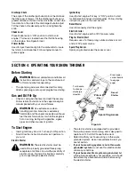
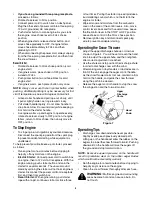
background image

7

Discharge Chute 

The angle of the discharge chute controls the distance 
that the snow is thrown. Tilt the discharge chute up for 
greater distance; tilt down for less distance. Loosen the 
hand knob on the side of the discharge chute to adjust. 
Tilt the chute to the desired position, and tighten the 
knob.

Choke Lever 

Place choke lever in “ON” position to start a cold 
engine. This lever is located near the throttle housing 
on the engine. See Figure 5 inset.

Primer Button

Used to inject fuel directly into the carburetor to insure 
fast starts in cold weather. Follow engine manual to 
prime engine.

Ignition Key 

Used to start engine. Put key  in “ON” position to start 
for both electric and recoil start engines. Follow starting 
instructions given in the next section.

Recoil Starter 

Used to manually start the engine.

Electric Starter 

Used to start engine with a 120V power source

Plug for Electric Start 

Requires use of a three-prong outdoor extension cord

and a 120V power source

Spark Plug Access

Spark plug located under the access cover.

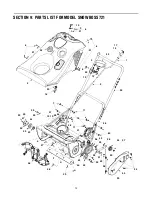
SECTION 4:  OPERATING YOUR SNOW THROWER

Before Starting

The spark plug wire was disconnected for safety. 
Attach spark plug wire to spark plug before starting.

Gas and Oil Fill-Up 

Check oil and gasoline level and add if necessary. 
Follow related instructions in the seperate engine 
manual packed with your snow thrower. 

To Start Engine 

Insert ignition key into slot. Turn key to ON position

.

Now follow the instructions below as it pertains to 
your unit.

Electric Starter 

Figure 6

The electric starter is equipped with a grounded 
three-wire power cord and plug, and is designed to 
operate on 120 volt AC household current.

Determine that your house wiring is a three-wire 
grounded system. Ask a licensed electrician if you 
are not certain. 

If your home wiring system is not a three-wire 
grounded system,

 do not use this electric starter 

under any conditions. 

If your home electrical system is grounded,

 but 

a three-hole receptacle is not available, one should 
be installed by a licensed electrician before using 
the electric starter.

WARNING: 

Read, understand, and follow all 

instructions and warnings on the machine and 
in this manual before operating.

WARNING: 

Use extreme care when 

handling gasoline. Gasoline is extremely 
flammable and the vapors are explosive. Never 
fuel the machine indoors or while the engine is 
hot or running. Extinguish cigarettes, cigars, 
pipes and other sources of ignition.

WARNING: 

The electric starter must be 

used with a properly grounded three-prong 
receptacle at all times to avoid the possibility of 
electric shock. Follow all instructions carefully 
prior to operating the electric starter.

Press auger
control handle
to engage 
auger

Turn handle 
to change 
discharge
direction 

Recoil 

Starter

Electric

Starter 

Key

Spark Plug Access

Primer

Choke

Lever

Summary of Contents for Snow Boss 721

Page 1: ...ster meeting applicable local or state laws if any If a spark arrester is used it should be maintained in effective working order by the operator In the State of California the above is required by la...

Page 2: ...te is explained below For future reference please copy the model number and the serial number of the equipment in the space below ENGINE INFORMATION The engine manufacturer is responsible for all engi...

Page 3: ...ector housing height to clear gravel or crushed rock surfaces 6 Disengage all clutch levers before starting the engine 7 Never attempt to make any adjustments while engine is running except where spec...

Page 4: ...Disengage all clutch levers and stop engine Wait until the auger impeller come to a complete stop Disconnect the spark plug wire and ground against the engine to prevent unintended starting before cle...

Page 5: ...the lower chute crank Insert the upper chute crank into the lower chute crank and align the holes Re insert the hairpin clip into the hole to secure the two chute cranks See Figure 2 Figure 2 Attachin...

Page 6: ...per handle the auger control handle is used to engage and disengage the auger The snow thrower is designed to propell by the rotation of the auger Pull the control handle back against the upper handle...

Page 7: ...rate engine manual packed with your snow thrower To Start Engine Insert ignition key into slot Turn key to ON position Now follow the instructions below as it pertains to your unit Electric Starter Fi...

Page 8: ...for several seconds The unusual sound made by spinning the starter will not harm engine or starter Disconnect the power cord from receptacle first and then from switch box Recoil Starter With engine...

Page 9: ...handle provides adjustment for belt tension To adjust disconnect the Z end of control cable from the bottom hole in the control handle See Figure 10 Hook the cable into the upper hole in control hand...

Page 10: ...ructions on page 9 Tighten securely Figure 14 Engine Refer to the separate engine manual for all engine maintenance procedures Check engine and snow thrower frequently for loose hardware and tighten a...

Page 11: ...spark plug 5 Clean spark plug readjust gap or replace 6 Prime engine four times 7 Wait at least ten minutes before starting Engine runs erratic 1 Unit running on choke 2 Fuel line blocked or stale fue...

Page 12: ...MODEL SNOW BOSS 721 15 9 21 6 6 21 6 21 4 20 16 24 14 17 23 3 8 22 10 13 2 1 25 60 7 18 11 11 19 12 5 5 5 26 27 28 29 30 31 32 33 34 35 36 37 38 39 40 33 41 42 43 44 45 46 47 48 49 50 42 49 51 52 53...

Page 13: ...riage Bolt 32 710 0642 TT Screw 1 4 20 x 0 75 33 710 0773 TT Screw 3 8 16 x 0 5 34 710 0896 AB Screw 1 4 14 x 0 625 35 710 1005 B Screw 1 4 14 x 0 5 36 711 0848A Axle Tube 37 712 0116 Jam Lock Nut 38...

Page 14: ...s Tank 19 751 0603 Fuel Cap 20 754 0101A V Belt 21 756 0416B V Pulley Half 22 756 0475 Pulley 23 784 0322 Engine Mount 24 784 0323 Support Bracket 25 784 0374 Support Plate Engine Mount Ref No Part No...

Page 15: ...0451 Carr Bolt 5 16 18 x 0 750 3 710 3015 Hex Screw 1 4 20 x 0 75 4 712 3027 Lock Nut 5 712 3068 Hex Lock Nut 6 720 0284 Hand Knob 7 731 0851A Flange Keeper Chute 8 731 0915B Lower Chute 9 731 0921 Up...

Page 16: ...these items b Routine maintenance items such as lubricants filters blade sharpening and tune ups or adjustments such as brake adjustments clutch adjustments or deck adjustments and normal deteriorati...

Reviews: