


Page 2
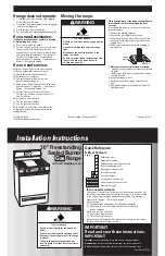
Product dimensions
Before you start...
Important: Observe all governing codes
and ordinances.
Do not obstruct flow of combustion and
ventilation air.
This installation must conform with all local
codes and ordinances.
In the absence of
local codes, installation must conform with
American National Standard, National Fuel
Gas Code ANSI Z223.1 — latest edition
*
.
It is the customer’s responsibility:
• To contact a qualified electrical installer.
• To assure that the electrical installation
is adequate and in conformance with
National Electrical Code, ANSI/NFPA 70
— latest edition
**
.
Cabinet opening dimensions
shown must be
used. Given dimensions are minimum
clearances.
When installing a range under existing cabinets
and the installation does not meet the minimum
cabinet clearances, install a range hood above
the cooktop to avoid burn hazards.
Proper installation
is your responsibility. A
qualified technician must install this range. Make
sure you have everything necessary for correct
installation. It is the installer’s responsibility to
comply with installation clearances specified on
the gas information label. The gas information
label and model/serial rating plate are located on
the frame behind the storage drawer.
***Note: 24" min. when bottom of wood
or metal cabinet is protected by not
less than 1/4" flame retardant mill-
board covered with not less than
No. 28 MSG sheet steel, 0.015"
stainless steel, 0.024" aluminum or
0.020" copper.
30" min. clearance between the top of
the cooking platform and the bottom
of an unprotected wood or metal
cabinet.
Contact a qualified
floor covering
installer to check
that the floor
covering can
withstand at least
200°F.
Use an insulated pad
or 1/4" plywood
under range if
installing range over
carpeting.
For minimum
clearance to top of
cooktop, see Note.***
Do Not pinch the power
supply cord between the
range and the wall.
Do Not seal the range to
the side cabinets.
2" min.
countertop
space to side
wall or other
combustible
material
This shaded area recommended
for installation of rigid gas pipe.
Flexible gas pipe and electrical
outlet are recommended in either
18" min.
clearance upper
cabinet to
countertop
13" max. upper
cabinet depth
If cabinet depth is greater
than 24", oven frame must
extend beyond cabinet
fronts by 1/2" min.
Cabinet dimensions/requirements
30-1/8" opening
width
30" min. cabinet
opening width
8 8 8
29-7/8" width
46-7/8"
overall
height
25"
36"
cooktop
height
27-1/8" depth
with handle
8"
4-1/2"
4-1/2"
2"
2"
17"
17"
8"
Grounded electrical
outlet
is required. See
“Electrical requirements,”
Page 3.
Proper gas supply
connection
must be
available. See “Gas
supply requirements,”
Page 3.
Check location where range will be installed. The range
should be located for convenient use in the kitchen.
Recessed installations must provide complete enclosure of
the sides and rear of range.
ALL OPENINGS IN THE WALL OR FLOOR WHERE RANGE IS
TO BE INSTALLED MUST BE SEALED.
IMPORTANT: Some cabinet and building materials are not
designed to withstand the heat produced by the oven for
baking and self-cleaning. Check with your builder or cabinet
supplier to make sure that the materials used will not
discolor, delaminate or sustain other damage.
WARNING: If the information in
this manual is not followed
exactly, a fire or explosion may
result causing property damage,
personal injury or death.
— Do not store or use gasoline or
other flammable vapors and
liquids in the vicinity of this or
any other appliance.
— WHAT TO DO IF YOU SMELL
GAS
• Do not try to light any
appliance.
• Do not touch any electrical
switch.
• Do not use any phone in your
building.
• Immediately call your gas
supplier from a neighbor’s
phone. Follow the gas
supplier’s instructions.
• If you cannot reach your
gas supplier, call the fire
department.
— Installation and service must
be performed by a qualified
installer, service agency or
the gas supplier.
Mobile home installation
The installation of this range must conform to the
Manufactured Home Construction and Safety Standards,
Title 24 CFR, Part 3280 (formerly the Federal Standard for
Mobile Home construction and Safety, Title 24, HUD, Part
280); or when such standard is not applicable, the Standard
for Manufactured Homes Installations (Manufactured Home
Sites, Communities and Setups), ANSI A225.1/NFPA 501A**,
or with local codes.
When this range is installed in a mobile home, it must be
secured to the floor during transit. Any method of securing
the range is adequate as long as it conforms to the standards
listed above.
Anti-tip bracket
The floor-mounted anti-tip bracket MUST be installed. To
install the anti-tip bracket supplied, see Pages 4-5 and the
anti-tip bracket template/instruction sheet.
Bracket must be securely mounted to
sub-floor. Thickness of flooring may
require longer screws to anchor
bracket to sub-floor. Longer screws
are available from your local hardware
store.
2 plastic
anchors
floor-mounted
anti-tip bracket
Not shown:
• literature pack
• orifice spuds
Parts supplied
2 screws
(#10 x 1-1/2")
Copies of the standards listed may be obtained from:
* CSA International
8501 East Pleasant Valley Road
Cleveland, Ohio 44131-5575
** National Fire Protection Association
One Batterymarch Park
Quincy, Massachusetts 02269
Your safety and the safety of
others are very important.
We have provided many important safety
message in this manual and on your
appliance.
Always read and obey all safety messages.
WARNING
This is the safety alert symbol.
This symbol alerts you to potential
hazards that can kill or hurt you and
others.
All safety messages will be preceded by the
safety alert symbol and the word “DANGER”
or “WARNING”. These words mean:
All safety messages will tell you what the
potential hazard is, tell you how to reduce
the chance of injury, and tell you what can
happen if the instructions are not followed.
You can be killed or seriously injured if
you don’t immediately follow instructions.
You can be killed or seriously injured if
you don’t follow instructions.
DANGER


