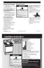


Natural gas conversion
1.
Complete installation sections A-C (Pages
4-5) before converting cooktop to natural gas.
Check that main gas supply line has been shut
off and the power supply cord is disconnected.
DO NOT REMOVE THE PRESSURE REGULATOR.
2.
Pressure regulator:
Remove storage
drawer and locate pressure regulator at back of
range. Remove plastic cover. Turn cap marked
“L.P.” on front of pressure regulator
counterclockwise with a wrench to remove.
Do
Not disturb or remove the spring beneath the
cap.
Turn the cap over and reinstall cap on
regulator so that the letter “N” is visible. Replace
plastic cover over cap.
5.
Broil burner:
Use 1/2" combination
wrench to loosen orifice hood away from pin
(approximately 2 to 2-1/2 turns). The burner
flame cannot be properly adjusted if this
conversion is not made.
6.
Reinstall the storage drawer. Complete
installation sections D through E, Pages 5-7.
Checking for proper cooktop burner and oven
flame is very important.
YOU MUST ADJUST “LOW” SETTING FOR
EACH COOKTOP BURNER. SEE STEP 16, PAGE 6.
Natural gas flames do not have yellow tips.
Page 8
6.
Reinstall the storage drawer. Complete
installation sections D through E, Pages 5-7.
Checking for proper cooktop burner and oven
flame is very important.
YOU MUST ADJUST “LOW” SETTING FOR
EACH COOKTOP BURNER. SEE STEP 16,
PAGE 6.
The small inner cone should have a very distinct
blue flame 1/4" to 1/2" long. The outer cone is not
as distinct as the inner cone. L.P. gas flames may
have a slightly yellow tip. If the flame is noisy or
blowing, it is getting too much air. If the flame is
soft and lazy, it is not getting enough air.
A brass orifice spud is located in the center of
each burner throat about 2" below the cooktop.
Apply masking tape to the end of a 5/16" nut
driver to fit snugly over the orifice spud. Press
driver down onto the spud of the left front burner
and remove by turning spud counter-clockwise
and lifting it out. Replace the Natural gas spud
with the appropriate L.P. gas spud shown in the
table.
Continue to replace the remaining orifice spuds,
one at a time. Place the Natural gas spuds on the
spud card on the back of the range for future use.
Replace burner caps using both screws, and
burner grates.
Surface
Propane
Orifice
Color
burner
Rate (BTU/hr) Number Marking
Left rear
8,000
L80
Green/Lt. Blue
Left front
11,000
L99
Green/Yellow
Right front
8,000
L80
Green/Lt. Blue
Right rear
5,000
L65
Green/Brown
L.P. Gas
4.
Oven burner:
Use 1/2" combination
wrench to turn the orifice hood down snug onto
pin (approximately 2 to 2-1/2 turns).
DO NOT
OVERTIGHTEN.
The burner flame cannot be
properly adjusted if this conversion is not made.
5.
Broil burner:
Use 1/2" combination wrench
to turn the orifice hood down snug onto pin
(approximately 2 to 2-1/2 turns).
DO NOT
OVERTIGHTEN.
The burner flame cannot be
properly adjusted if this conversion is not made.
orifice hood
hood
orifice hood
pin
L.P. gas
decrease gas
decrease
flame size
Natural gas
increase gas
increase flame size
pre-set at factory
for Natural gas
L.P.
cap
washer
pressure
regulator
Nat. gas
L.P. gas
pressure
regulator
Natural
plastic
cover
plastic
cover
Locate the brass orifice spuds in the center of each
burner throat about 2" below the cooktop. Apply
masking tape to the end of a 5/16" nut driver to fit
snugly over the orifice spud. Press driver down
onto the spud of the left front burner and remove
by turning spud counter-clockwise and lifting it
out. Replace the L.P. gas spud with the appropriate
Natural gas spud shown in the table.
Continue to replace the remaining orifice spuds,
one at a time. Place the L.P. gas spuds on spud
card on the back of the range for future use.
Replace burner caps, using both screws and
burner grates.
Surface
Natural Gas Orifice
Color
burner
Rate (BTU/hr) Number Marking
Left rear
8,000
N139
Blue/Black
Left front
12,000
N176
Blue/Red
Right front
9,500
N151
Blue/Brass
Right rear
5,000
N112
Blue/White
Natural Gas
4.
Oven burner:
Use 1/2" combination
wrench to loosen the orifice hood away from pin
(approximately 2 to 2-1/2 turns). The burner
flame cannot be properly adjusted if this
conversion is not made.
orifice hood
hood
orifice hood
pin
L.P. gas
decrease gas
decrease
flame size
Natural gas
increase gas
increase flame size
pre-set at factory
for Natural gas
3.
Surface
Burners:
Remove burner
caps. Use a
Phillips or
Quadrex
screwdriver to
remove the two
screws holding
the burner head down. Lift the
burner head off the cooktop to uncover the
orifice spud holder. The orifice spud is recessed
in the holder.
Note: Reinstall one of the screws through the
range cooktop to hold orifice spud holder in place
while removing and replacing orifice spuds.
orifice
number
5/16"
nut driver
orifice spud.
Replace orifice
spud with the
number listed
in chart.
burner
assembly
Locate the L.P. gas orifice spuds
on spud card on back of range.
Orifice spuds are stamped with
a number and marked with two
color dots and a groove.
L.P. gas
orifice spud
reinstall
one of the
screws
orifice
spud
orifice
spud
holder
spark electrode
range cooktop
groove
Natural gas
orifice spud
Locate the Natural gas orifice spuds on
the spud card on the back of the range.
Orifice spuds are stamped with a
number and marked with two color dots.
orifice
number
5/16"
nut driver
orifice spud.
Replace orifice
spud with the
number listed
in chart.
burner
assembly
3.
Surface
Burners:
Remove burner
caps. Use a
Phillips or
Quadrex
screwdriver to
remove the two
screws holding
the burner head down. Lift the
burner head off the cooktop to uncover the
orifice spud holder. The orifice spud is recessed
in the holder.
Note: Reinstall one of the screws through the
range cooktop to hold orifice spud holder in place
while removing and replacing orifice spuds.
reinstall
one of the
screws
orifice
spud
orifice
spud
holder
spark electrode
range cooktop


