1
40" ELECTRIC RANGE INSTALLATION INSTRUCTIONS
P/N 318201707 (1201) Rev. A
Printed in Canada
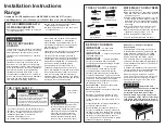
**NOTE:
24" (61 cm) minimum clearance between the
cooktop and the bottom of the cabinet when the bottom
of wood or metal cabinet is protected by not less than
1/4" (0.64 cm) fl ame retardant millboard covered with
not less than No. 28 MSG sheet metal, 0.015" (0.4 mm)
stainless steel, 0.024" (0.6 mm) aluminum, or 0.020" (0.5
mm) copper.
30" (76.2 cm) minimum clearance when the cabinet is
unprotected.
Do not pinch the power supply cord between the range
and the wall.
Do not seal the range to the side cabinets.
B
27 ¾"
with handle
(70.5 cm)
36"
feet extended
(91.4 cm)
47 ¼" Max.
(120 cm)
43 ¾"
(111.1 cm)
with larger
door open
13" Min.
(33 cm Min.)
18" Min.
(45.7 cm Min.)
24" Min.
(61 cm Min.)
40 1/8" Min.
(101.9 cm Min.)
30" Min.**
(76.2 cm Min.)
Grounded
Wall Outlet
2 1/2" Min.
(6.4 cm Min.)
On left side
only, if there is a
wall
A. HEIGHT
B. WIDTH
C. DEPTH TO
FRONT OF RANGE
D. DEPTH WITH
DOOR OPEN
E. MINIMUM
CUTOUT WIDTH
F. HEIGHT OF
COUNTERTOP
36" (91.4 cm)
40 1/8" (101.9 cm)
25 ½" (64.8 cm)
43¾" (111.1 cm)
40¼" (102.2 cm)
36" (91.4 cm) standard
35 3/8" (90 cm) min.
INSTALLATION AND SERVICE MUST BE PERFORMED BY A QUALIFIED INSTALLER.
IMPORTANT: SAVE FOR LOCAL ELECTRICAL INSPECTOR'S USE.
READ AND SAVE THESE INSTRUCTIONS FOR FUTURE REFERENCE.
FOR YOUR SAFETY: Do not store or use gasoline or other
fl ammable vapors and liquids in the vicinity of this or any other appliance.
United States