page 1 - 5
EDGE Network / Jan 2016
G E N E R A L I N F O R M A T I O N
EDGE Delay Controls
The EDGE DELAY interval is adjustable to accommodate various parameters of
the IP radio link. A minimum number of samples is required to overcome the duplexing
interval of the link. The control setting of upwards of one second is more for testing and
confirmation that the appropriate connections and data paths have been chosen. All eight
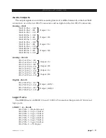
EDGE Destinations, four BUFFERS, plus two analog outputs, and two AES outputs
feature a DELAY control that may be adjusted using the EDGE GUI.
Return Path Audio
In both cases, installation of an Edge at the Studio or Transmitter site, there are means
to bring a return audio feed from the Transmitter back to the Studio.
In the “Studio EDGE” case where a BLADE exists at the Transmitter, the desired Return
audio Source is wired to audio inputs of the TX site BLADE which appear in Navigator
as a standard BLADE Source stream. This .25mS packet Source stream is then routed to
an EDGE BUFFER destination. The BUFFER in turn feeds a variable DELAY whose
output appears as a Source in Navigator. That buffered source can now be connected to
any BLADE in the system where the audio will again be buffered and played out with
additional delay. The latency of the audio in this return path will be 100 msec or more.
The BLADE buffers 5 msec packets upwards of 100 msec, and then the DELAY setting
of the EDGE would be in addition to that.
In the “TX EDGE” case, return audio would simply be connected into the EDGE
inputs, Analog or AES, and those sources would be available to any BLADE back in
the Studio with the corresponding latency. Note that these physical audio inputs are only
available as 5msec packets.
Analog and Digital Audio I/O Connections
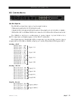
The EDGE provides two stereo analog inputs and two stereo analog outputs on XLR
connectors. A pair of AES inputs and a pair of AES outputs are also available on RJ-45
connectors. These inputs are fed through a fixed 100mS buffer and available in Navigator
as Sources.
In a Studio EDGE installation, the analog and AES I/O may not be required.
In a Transmitter EDGE installation, Analog or AES outputs would be utilized to feed
an air chain, while the analog or AES inputs may be used for return path audio.
Synchronization – PLL Settings
The EDGE and BLADE both use Ethernet packets for sample rate clock synchronization.
The IP radio inherently adds a substantial jitter to these timing reference packets.
In order to overcome the jitter, the error integration interval and overall loop locking must
be extended significantly. A PLL MODE selection is provided to accommodate for this.
Studio EDGE Model:
• The EDGE “PLL MODE” is set for LOCAL.
• The TX side BLADE set to SLOW PLL mode for that unit only.


