


page 10 – 3
A-5000 / Nov 98
L I N E P R E S E L E C T O R M O D U L E
Hook-Ups
LSD-500 Line Preselector Module
Two DB-25 connectors that wire pin-for-pin to matching DB-25s
on the LSR-500 chassis rear. The upper connector is for control; the
lower for power. See pinout drawing on page 10-6 for signals.
LSR-500 Audio Inputs
These are for analog stereo (+4dBu balanced) and digital (AES)
signals; there are three DB-25 input connectors on the chassis rear:
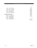
ANALOG AUDIO INPUTS 1-4:
Pin 25 – Line 1 Lt In SH
Pin 24 – Line 1 Lt In HI
Pin 12 – Line 1 Lt In LO
Pin 11 – Line 1 Rt In SH
Pin 10 – Line 1 Rt In HI
Pin 23 – Line 1 Rt In LO
Pin 22 – Line 2 Lt In SH
Pin 21 – Line 2 Lt In HI
Pin 9 – Line 2 Lt In LO
Pin 8 – Line 2 Rt In SH
Pin 7 – Line 2 Rt In HI
Pin 20 – Line 2 Rt In LO
Pin 19 – Line 3 Lt In SH
Pin 18 – Line 3 Lt In HI
Pin 6 – Line 3 Lt In LO
Pin 5 – Line 3 Rt In SH
Pin 4 – Line 3 Rt In HI
Pin 17 – Line 3 Rt In LO
Pin 16 – Line 4 Lt In SH
Pin 15 – Line 4 Lt In HI
Pin 3 – Line 4 Lt In LO
Pin 2 – Line 4 Rt In SH
Pin 1 – Line 4 Rt In HI
Pin 14 – Line 4 Rt In LO
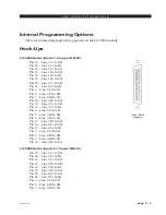
Typical DB-25
connector
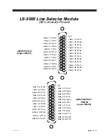
POWER
ANALOG
1
DIG
Model LSR-500 Line Selector
8-Line Analog/Digital Rackmount Switcher
2
3
4
5
6
7
8
LINE
ANALOG/DIG SELECT
CONTROL LOGIC
DC POWER
DIGITAL OUT
DIGITAL INPUTS
AUDIO OUT
AUDIO INPUTS 5-8
AUDIO INPUTS 1-4
CAUTION - TO AVOID ELECTRIC SHOCK REFER SERVICE TO QUALIFIED TECHNICIAN
5
8
4
3
2
1
6 7
The LSR-500 Rackmount Switcher Unit (front & rear)