


page 5 – 4
D500 / Jul 98
C O N T R O L R O O M M O D U L E
Hook-Ups
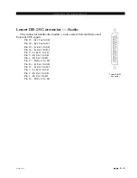
As stated before, all user wiring to and from the CRD-500 module takes
place at two DB-25 multi-pin connectors mounted directly beneath the
module on the console mainframe’s bottom pan.
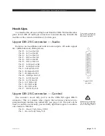
Upper DB-25 Connector — Audio
Includes cue, headphone and control room outputs. All audio signals
are +4dBu balanced, analog stereo.
Pin 25 – Lt Cue Out SH
Pin 24 – Lt Cue Out HI
Pin 12 – Lt Cue Out LO
Pin 11 – Rt Cue Out SH
Pin 10 – Rt Cue Out HI
Pin 23 – Rt Cue Out LO
Pin 22 – Lt Hdpn Out SH
Pin 21 – Lt Hdpn Out HI
Pin 9 – Lt Hdpn Out LO
Pin 8 – Rt Hdpn Out SH
Pin 7 – Rt Hdpn Out HI
Pin 20 – Rt Hdpn Out LO
Pin 19 – Lt CR Out SH
Pin 18 – Lt CR Out HI
Pin 6 – Lt CR Out LO
Pin 5 – Rt CR Out SH
Pin 4 – Rt CR Out HI
Pin 17 – Rt CR Out LO
Upper DB-25 Connector — Control
The console’s on-air tally port is on the CRD-500 upper DB-25
connector. This is a simple relay closure that activates whenever pro-
grammed input modules are turned ON (see page 2-4). The port can be
used to control an externally powered tally light that requires a continu-
ous closure to function.
Pin 14 – On-Air Tally Relay COM
Pin 1 – On-Air Tally Relay N.O.
Maximum current through
the on-air tally relay clo-
sure is 2 amps @30VDC.
!
Typical DB-25
connector
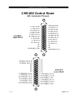
See pinout drawing on
page 5-6 for all wiring con-
nections at a glance.
A-5000 / Nov 98