


page 5 – 2
D500 / Jul 98
C O N T R O L R O O M M O D U L E
Control Room Module
(CRD-500)
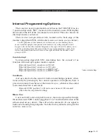
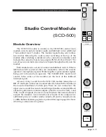
Module Overview
The CRD-500 module is the A-5000 console operator’s monitor
module. It allows him to listen to the console’s four stereo outputs
(PGM, AUD, AUX & UTL) as well as two external stereo line level
inputs brought directly into the module. Source SELECT switching for
these signals is at the top of the module.
The CRD-500 also houses console HEADPHONE and CONTROL
ROOM circuits, which follow the source selection switches.
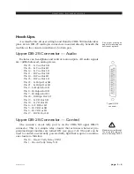
There are two types of headphone output: the +4dBu balanced output at
the module’s upper DB-25 connector (pre-level control), and two head-
phone jacks mounted left and right on the front of the lower mainframe pan,
which are actually outputs from a built-in headphone amplifier. It is this
built-in amp that is controlled by the module’s front panel HEAD-
PHONE level control.
The CUE master level control is right in the center of the module;
this sets the level of the console’s cue signal.
Whenever CUE is activated elsewhere on the console (stereo line
inputs, the superphone module or for studio talkback) its signal will appear
at the console’s built-in left and right cue speakers mounted in the meter-
bridge. Depending on how the CRD-500 module has been programmed, cue
can also interrupt the control room monitor speakers and/or the console
operator’s headphone. The way Cue interrupts the module’s headphone and
CR outputs is determined by an internal PCB-mounted dipswitch. See “Cue
Interrupt” on next page.
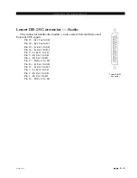
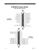
All user wiring to and from the CRD-500 module takes place at
DB-25 multi-pin connectors mounted directly beneath the module on
the console mainframe’s bottom pan. There are two connectors: the
upper one (towards the console meterbridge) handles audio outputs and
the console on-air tally control signals; the lower (near the console
armrest) accepts the two external source inputs. All audio connections
are stereo line level analog signals (+4dBu balanced). A pinout
drawing on page 5-6 shows all wiring connections at a glance.
A-5000 / Nov 98
CONTROL ROOM
8
0
9
7
6
5
4
3
2
1
10
8
0
10
9
7
6
5
4
HEADPHONE
3
2
1
8
0
10
9
7
6
5
4
3
2
1
CUE
EXTERNAL
STEREO
SELECT
CONTROL ROOM
1
2
PGM
AUD
AUX
UTL
ON