


page 8 – 7
A-5000 / Nov 98
S U P E R P H O N E I N P U T
Drop Cue2
SW3 position 4 - The DROP2 switch will also drop Caller 2 from
CUE with this dipswitch active.
Dipswitch SW4 Functions
Tallies
Turning the module ON can activate a remote tally indicator. There are
three tally control lines: on-air, tally 2 and tally 3. The first three positions
of dipswitch SW4 (to the left of the fader) program these functions:
SW4 position 1 activates the on-air tally control line
SW4 position 2 activates tally 2 relay on the SCD-500 module
SW4 position 3 activates tally 3 relay on the SCD-500 module
Cue Dropout
Dipswitch SW4 position 4, when activated, will cause CUE (i.e.,
Answer CUE/TB buttons 1 & 2) to turn off when the module’s ON/START
switch is pressed. This is the factory default setting.
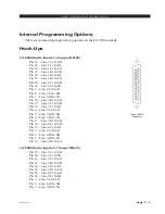
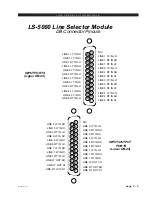
Hook-Ups
As stated before, all user wiring to and from SPN-5000 modules takes
place at DB-25 multi-pin connectors mounted directly beneath each module
on the console mainframe’s bottom pan. There are two connectors per
module: the upper one (towards the console meterbridge) handles audio
input signals and logic contol signals; the lower (near the console armrest)
audio outputs and logic control signals. A pinout drawing on page 8-9 shows
all wiring connections at a glance.
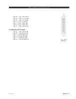
Audio and Control Connections (upper DB-25)
These include External In and station Hybrid 1 & 2 inputs. All are +4dBu
balanced analog mono and remote tape machine START/STOP ports.
Pin 25 – Ext In SH
Pin 24 – Ext In HI
Pin 12 – Ext In LO
Pin 22 – Hybrid 1 In SH
Pin 21 – Hybrid 1 In HI
Pin 9 – Hybrid 1 In LO
Pin 8 – Hybrid 2 In SH
Pin 7 – Hybrid 2 In HI
Pin 20 – Hybrid 2 In LO
Pin 15 – Start/Stop Common
Pin 14 – Stop
Pin 1 – Start
Pins 2,5,11,13,16 and 19 – Audio Ground
Typical DB-25
connector
Remote tallies are
hooked-up to the console
at the Control Room mod-
ule (CRD-500) and the
Studio Control Module
(SCD-500)