


page 4 – 3
D500 / Jul 98
O U T P U T M O D U L E S
Internal Programming Options
Insert Bypass
All internal programming jumpers on OM-5000 modules are for factory
use only. The INSERT BYPASS slide switch SW1, located near the top of the
PCB just above the four front panel analog trimpots is used to bypass the insert
if it will not be wired externally. The factory default for this switch is “down”;
i.e., the module’s PGM insert points are bridged. To use the PGM insert points
(located on the upper DB-25 connector) throw the switch “up”.
For the purposes of this manual, we will assume you are holding the removed
module upright, component side towards you, with gold-plated card fingers to the
left and the module faceplate to the right.
Hook-Ups
As stated before, all user wiring to and from OM-5000 modules takes place
at two DB-25 multi-pin connectors mounted directly beneath the module on
the console mainframe’s bottom pan.
Master Output Module A:
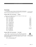
Upper DB-25 Connector - Analog Audio
Includes Program, Auxiliary outputs and Program insert points. All
signals are +4dBu balanced.
Pin 25 – PGM Lt Out SH
Pin 24 – PGM Lt Out HI
Pin 12 – PGM Lt Out LO
Pin 11 – PGM Rt Out SH
Pin 10 – PGM Rt Out HI
Pin 23 – PGM Rt Out LO
Pin 22 – AUX Lt Out SH
Pin 21 – AUX Lt Out HI
Pin 9 – AUX Lt Out LO
Pin 8 – AUX Rt Out SH
Pin 7 – AUX Rt Out HI
Pin 20 – AUX Rt Out LO
Pin 19 – PGM Lt Insert Out SH
Pin 18 – PGM Lt Insert Out HI
Pin 6 – PGM Lt Insert Out LO
Pin 5 – PGM Rt Insert Out SH
Pin 4 – PGM Rt Insert Out HI
Pin 17 – PGM Rt Insert Out LO
Pin 16 – PGM Lt Insert In SH
Pin 15 – PGM Lt Insert In HI
Pin 3 – PGM Lt Insert In LO
Pin 2 – PGM Rt Insert In SH
Pin 1 – PGM Rt Insert In HI
Pin 14 – PGM Rt Insert In LO
Typical DB-25
connector
Insert points are normally by-
passed at the factory. See “In-
sert Bypass” (preceding section)
if you intend to use these points.
A-5000 / Nov 98