background image

I

NSTALLATION

3-7

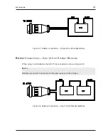
Figure 3-7: Battery Connections — Single 24-Volt Standby Battery

B

ATTERY

 C

ONNECTIONS

 — D

UAL

 12-V

OLT

 S

TANDBY

 B

ATTERIES

When using 12-volt batteries, the SE 3718 is connected as shown in Figure 3-8.

N

OTE

Batteries connected in series must be the same type and fully charged.

Figure 3-8: Battery Connections — Dual 12-Volt Standby Batteries

Summary of Contents for SE 3718S

Page 1: ...5452 Betsy Ross Drive Santa Clara CA 95054 1184 408 727 5170 FAX 408 727 6707 P N 66109090001 Rev C SE 3718S UNINTERRUPTABLE POWER SUPPLY ...

Page 2: ...ed and used in accordance with the instructions herein may cause harmful interference to radio communications However there is no guarantee that interference will not occur in a particular installation If this equipment does cause harmful interference to radio or television reception which can be determined by turning the equipment off and on the user is encouraged to try to correct the interferen...

Page 3: ...ms have been approved by WSE e g coaxial cables batteries etc and VI the equipment has been installed the installation supervised or installation tested by an authorized WSE dealer WSE shall at its option either repair or replace free of charge the equipment found upon WSE s inspection to be so defective or if agreed upon refund the purchase price less a reasonable allowance for depreciation in ex...

Page 4: ...IV SE 3718S UNINTERRUPTABLE POWER SUPPLY ...

Page 5: ...ching Power Supply Circuitry 2 3 Battery Charger Circuitry 2 3 Secondary Switching Power Supply 2 4 Control and Indicators Circuitry 2 4 Indicator LEDs 2 4 Controls 2 4 Fuses 2 5 Connectors 2 5 Section 3 Installation 3 1 Location and Mounting 3 1 Wiring Requirements 3 1 ACU Cable Connections 3 1 Lock Power Wiring Connections 3 3 Battery Cable Connections 3 6 Battery Connections Single 24 Volt Stan...

Page 6: ...VI SE 3718S UNINTERRUPTABLE POWER SUPPLY ...

Page 7: ...ed to conflict with and or supplement the building codes electrical codes or safety codes to which any given installation must conform CONFIGURATION The SE 3718S is available in one configuration which accommodates both 115 and 230 volt AC power input Lock voltage is switch selectable between 12 and 24 volts Backup battery power is standardized at 24 volts nominal SYSTEM OVERVIEW The SE 3718S is a...

Page 8: ...w Therefore any devices in addition to those listed above may cause the 3718S to be damaged or operate incorrectly As noted installation personnel should be careful to avoid overloading the system Because of the many lock types available and the dynamic nature of their power requirements and also because of the many system configurations available it is impossible to state exactly the number of lo...

Page 9: ...e sollen nur von qualifiziertem Personal ausgewechseld wirden Die Batterien können elektrische Schlag verursachen Bitte beachten Sie die Sicherheitsmassnahmen Achtung Nur geeignete Batterien und Menge der zufolgende Tabelle 1 1 benützen INSTRUCCIONES DE SEGURIDAD Guardar estas instrucciones importantes No obstruir los conductos de ventilación No hay piezas que requieran servicio del cliente dentro...

Page 10: ...ffet Ne pas masquer les trous d aération Ne contient aucune pièce pouvant être réparée par l utilisateur Confier toute réparation à un technicien qualifié Afin de prévenir tout risque d incendie remplacer les fusibles en respectant les types et la valeur recommandés TABLE 1 1 RECOMMENDED STANDBY BATTERIES MANUFACTURER DESCRIPTION PART NUMBER Eagle Picher 12 V 31 amp hour CFM12V33 sealed lead acid ...

Page 11: ...ION 2 1 SECTION 2 DESCRIPTION The SE 3718S Uninterruptable Power Supply Figures 2 1 and 2 2 provides the requisite input AC and DC power for the WSE 700 and 800 series ACUs SE 3718S Uninterruptable Power Supply ...

Page 12: ...y 6 in 15 2cm wide by 4 in 10 2cm high Unit weight is 9 2 lbs 3 4kg As shown in Figures 2 1 and 2 2 the SE 3718S consists of a chassis with mounting flanges at each side and a body perforated on three sides for efficient convection cooling Status indicators and user serviceable parts are conveniently located on the top surface ...

Page 13: ...he optional backup battery if it is installed takes over There are no user serviceable parts or fuses associated with the primary switching power supply BATTERY CHARGER CIRCUITRY The battery charger circuit has two basic functions In normal operation it takes power from the primary switching power supply and provides a controlled charging current to the optional backup battery During power failure...

Page 14: ...d impending battery failure in case of long term outages INDICATOR LEDS As shown in Figure 2 2 five LEDs are mounted on the SE 3718S control panel These LEDs are controlled by the control and indicator circuitry and function as follows AC ON Lights when unit connected to and operating from AC power BATTERY CONNECTED Lights to indicate presence of battery BATTERY FULL Lights to indicate fully charg...

Page 15: ... SB Battery CONNECTORS SYSTEM POWER 14 pin circular Provides all power needed by an ACU BATTERY 4 pin circular Provides power to and from the backup battery AUX POWER 4 pin Phoenix Provides 12V of auxiliary power for use with optional user specified equipment LOCK POWER 3 pin Phoenix Provides either 12V or 24V switch selectable lock power Figure 2 4 Control and Indicators Detail ...

Page 16: ......

Page 17: ...d below the ACU as the heat radiated by it can raise the ACU temperature above the prescribed limit Airflow through the ventilation holes should be unrestricted Ideally the unit should be mounted horizontally to allow air to flow upward through the unit If the cabinet temperature can rise to 120o F 49o C cut ventilation holes in both the top and bottom of the enclosure If this is insufficient a co...

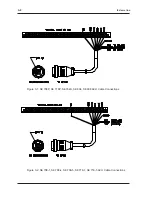
Page 18: ...3 2 INSTALLATION Figure 3 1 SE 708P SE 718P SE 764S SE 804 SE 808 ACU Cable Connections Figure 3 2 SE 708 1 SE 708 4 SE 708 5 SE 718 1 SE 718 5 ACU Cable Connections ...

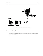
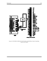
Page 19: ...INSTALLATION 3 3 Figure 3 3 SE 818 ACU Cable Connections LOCK POWER WIRING CONNECTIONS ACU lock power connections between the SE 3718S and the various ACUs are shown in Figures 3 4 3 5 and 3 6 below ...

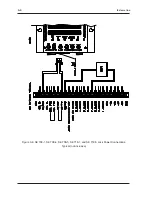
Page 20: ...3 4 INSTALLATION Figure 3 4 SE 708 1 SE 708 4 SE 708 5 SE 718 1 and SE 718 5 Lock Power Connections Typical not inclusive ...

Page 21: ...INSTALLATION 3 5 Figure 3 5 SE 708P SE 708S SE 718P SE 804 and SE 808 Lock Power Connections Typical not inclusive ...

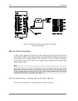
Page 22: ...settings and use either two 12 volt or a single 24 volt battery Connections between the SE 3718S and the various battery configurations using the battery cable are shown below NOTE Discharged batteries or batteries of the wrong type are not recognized and internally the SE 3718S automatically disconnects itself from them Ensure that the batteries are fully charged and are the correct type or equiv...

Page 23: ...Battery BATTERY CONNECTIONS DUAL 12 VOLT STANDBY BATTERIES When using 12 volt batteries the SE 3718 is connected as shown in Figure 3 8 NOTE Batteries connected in series must be the same type and fully charged Figure 3 8 Battery Connections Dual 12 Volt Standby Batteries ...
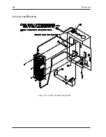
Page 24: ...3 8 INSTALLATION LOCATION AND MOUNTING Figure 3 9 Location and Mounting Details ...

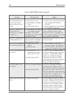
Page 25: ...s CUSTOMER SERVICE If a problem with an SE 3718S cannot be rectified by replacing a faulty cable interface wiring or fuse call WSE Customer Support for a return authorization Units returned without a return authorization cannot be accepted Return units to Westinghouse Security Electronics 5452 Betsy Ross Drive Santa Clara CA 95054 1184 TROUBLESHOOTING GUIDE A troubleshooting guide follows with Tab...

Page 26: ...ther indicators are on charged depends on battery size charge state 2 Battery is faulty 2 Try another battery ensure battery is the right type Call WSE for disposition SYSTEM OK indicator is out 1 Any combination of the Turn unit off disconnect system power AC ON is lit following fuses are blown connector Replace any blown fuses turn 10V 20V 18V 24V unit back on If SYSTEM OK indicator remains out ...

Reviews: